
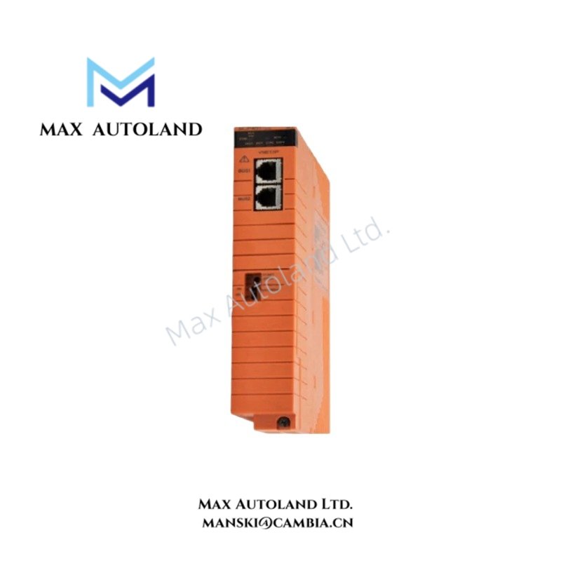
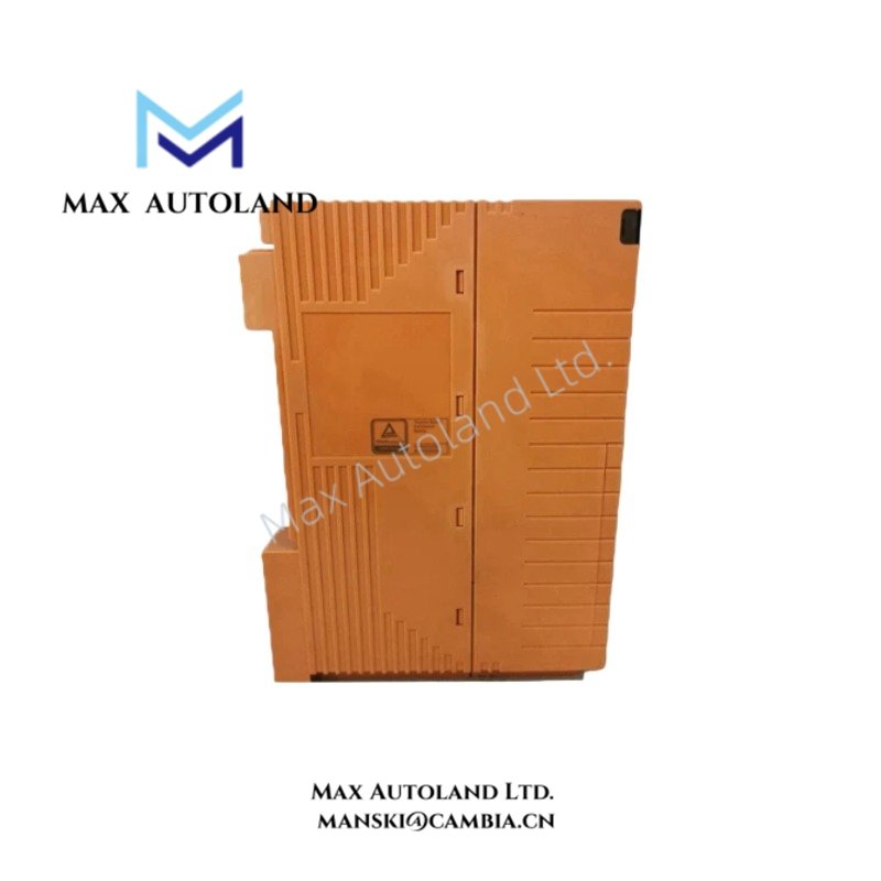
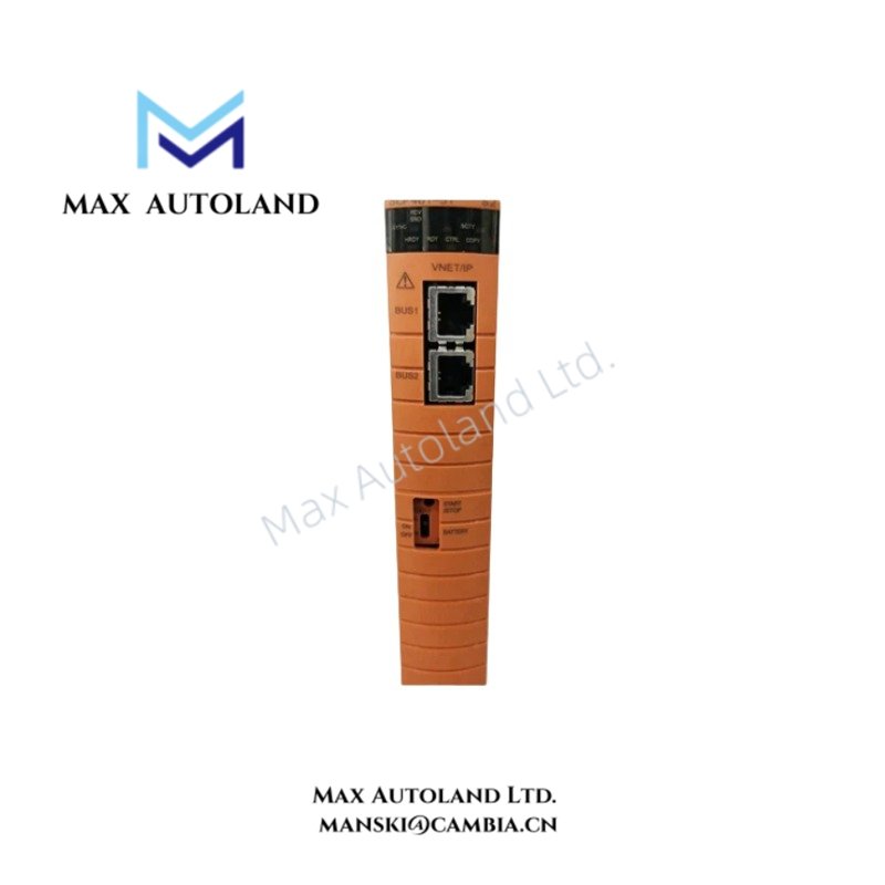

Overview
Hardware Specifications
| Parameter | Specification |
|---|---|
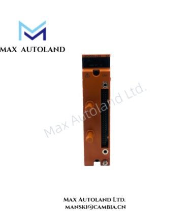
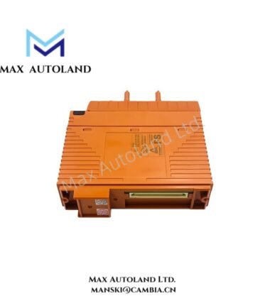
| Model | SCP451-53 |
| Brand | Yokogawa |
| Series | ProSafe-RS |
| Product Type | Safety Control Modules |
| Output Channels | 4 |
| Output Signals | 0-20 mA, 4-20 mA, 0-10 VDC, 1-5 VDC |
| Output Resolution | 12-bit |
| Output Accuracy | +/- 0.1% of span |
| Load Resistance | 0-1000 ohm for current; 0-1 Mohm for voltage |
| Isolation | 500 Vrms, output to ground |
| Weight | Approx. 1.5 kg |
| Dimensions | 123 x 122 x 100 mm |
| Operating Temp | -10 to +55 deg C |
| Storage Temp | -40 to +85 deg C |
| Ambient Humidity | 5-95% RH, non-condensing |
| Power Consumption | 10 W maximum |
| Functional Safety | SIL 3 claim requires model-specific verification |
| Certifications | ATEX, IECEx, UL, CSA and CE claims require verification |
Safety System Compatibility and Signal Verification
The supplied description associates SCP451-53 with analog output processing and ProSafe-RS safety control. Before selecting this module for a safety loop, verify its official product designation, supported signal types, channel configuration and applicable safety certification.
Do not assume that the listed current and voltage outputs, isolation rating or SIL capability apply to SCP451-53 without a matching manufacturer datasheet. The module’s role as an analog output device also remains unconfirmed by the supplied information.
Frequently Asked Questions
Q: Does the SCP451-53 support four analog output channels?
A: The supplied description lists four channels, but this specification requires confirmation against the official Yokogawa documentation for the exact model.
Q: Can the SCP451-53 directly drive a 4-20 mA control loop?
A: The supplied information lists 4-20 mA output. Confirm the actual output function, load limits, wiring arrangement and compatible field devices before connecting the module to a control loop.
Q: Is the SCP451-53 certified for SIL 3 applications?
A: The supplied description claims SIL 3 compliance. Verify the exact model’s safety certification and permitted system configuration in the applicable manufacturer’s safety manual before using it in a safety instrumented function.
Field Installation Guidelines
- Confirm the complete model number and hardware revision against the equipment documentation before installation.
- Verify the module’s designated slot, compatible base unit and supported system configuration.
- Isolate power according to the site’s approved maintenance procedure before handling or wiring the hardware.
- Check terminal assignments and field signal requirements against the official wiring diagram. Do not rely on unverified output specifications.
- Route analog signal cables separately from high-voltage and high-current wiring where practical. Apply the cabinet’s documented shielding and grounding practices.
- Confirm loop polarity, field-device compatibility and load requirements before energizing the circuit.
- Complete the prescribed system diagnostics and functional tests before returning the equipment to service
YOKOGAWA Top Products
Customers Also Viewed



Reviews
There are no reviews yet.