
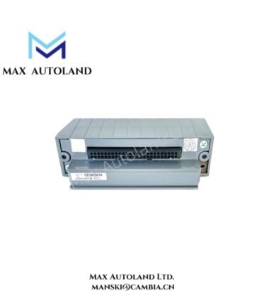
Overview
Hardware Specifications
| Parameter | Specification |
|---|---|
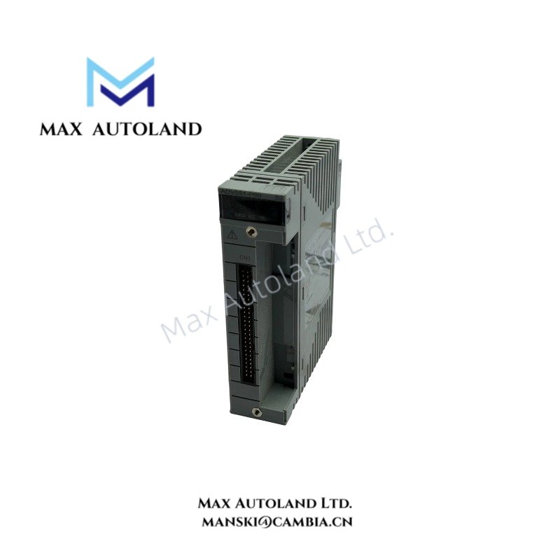
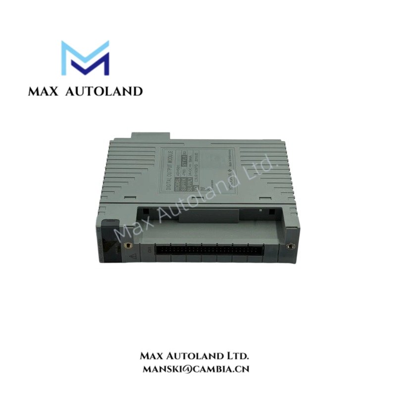
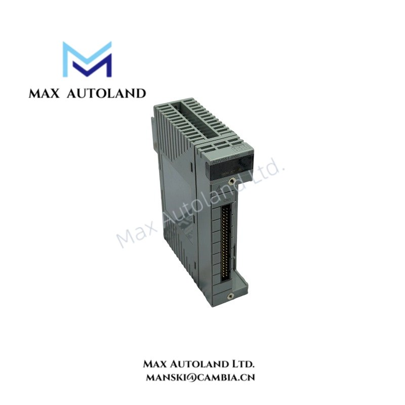
| Model | NFDV551 |
| Full Model | NFDV551-P60 |
| Brand | Yokogawa |
| Product Type | Digital Output Module |
| Origin | Not specified in the provided data |
| Number of Output Channels | 32 |
| Rated Applied Voltage | 24 VDC |
| Load Voltage | 24 VDC, 50 mA |
| Field Power Supply Voltage Range | 20.4 to 26.4 VDC |
| Output Format | Current sink |
| Maximum Output ON Voltage | 2 VDC |
| Maximum OFF-State Leakage Current | 0.1 mA |
| Maximum Load Current | 100 mA per channel at 26.4 V |
| Withstanding Voltage | 500 VAC between commons; other test details are not fully specified |
| Status Output | ON/OFF status reporting |
| Output Fallback | HOLD or OFF |
| Output Response Time | 3 ms or less for status output |
| Power Consumption | 700 mA at 5 VDC; 60 mA at 24 VDC field power supply |
| Weight | 0.2 kg |
| External Connection | Pressure clamp terminal block or MIL connector cable |
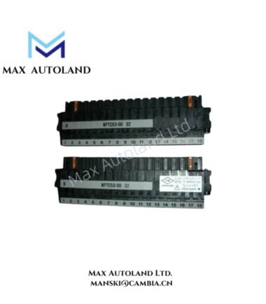
| Compatible Terminal Block | NFTD55-00 or NFTD55-10 |
| Compatible Connector Cover | NFCCC01 |
Digital Output Electrical Characteristics
The NFDV551 uses current-sink outputs to control connected field loads. Each channel has a maximum specified load current of 100 mA at 26.4 V. The stated load voltage is 24 VDC at 50 mA.
The maximum ON-state voltage is 2 VDC, while the maximum OFF-state leakage current is 0.1 mA. These values should be considered when selecting field devices and checking their input thresholds.
The output fallback function provides two documented modes:
- HOLD: Retains the current output states.
- OFF: Sets all output channels to the OFF state.
The appropriate fallback mode depends on the control sequence and the required response to a system fault or output interruption.
Frequently Asked Questions
Q: How many output channels does the NFDV551 provide?
A: The module provides 32 digital output channels with a rated applied voltage of 24 VDC.
Q: What field wiring interfaces are supported?
A: The documented connection options include pressure clamp terminal blocks and MIL connector cables. Compatible options include NFTD55-00, NFTD55-10, and NFCCC01, depending on the selected connection configuration.
Q: What happens to the outputs when fallback control is activated?
A: The module supports HOLD and OFF modes. HOLD retains the current output states, while OFF sets all output channels to the OFF state. Confirm the system configuration before commissioning.
Field Installation Guidelines
- Verify the module configuration. Confirm the complete model designation and suffix codes against the installed hardware and system documentation.
- Check field supply voltage. Maintain the specified field power supply range of 20.4 to 26.4 VDC.
- Verify output load requirements. Check the field device voltage, input threshold, and current demand against the module’s electrical limits.
- Select the correct terminal interface. Confirm compatibility between the module, pressure clamp terminal block, or MIL connector cable before wiring.
- Separate signal and power wiring. Route field signal conductors away from high-current and noise-generating circuits where practical.
- Inspect polarity and common connections. Verify wiring against the manufacturer’s terminal assignments before energizing the module.
- Validate fallback behavior. Test HOLD and OFF operation under an approved commissioning procedure. Confirm that the selected behavior matches the process control requirements.
- Check output operation. Verify channel states and connected field-device responses during commissioning. Do not exceed the specified channel load limits.
YOKOGAWA Top Products
Customers Also Viewed




Reviews
There are no reviews yet.