
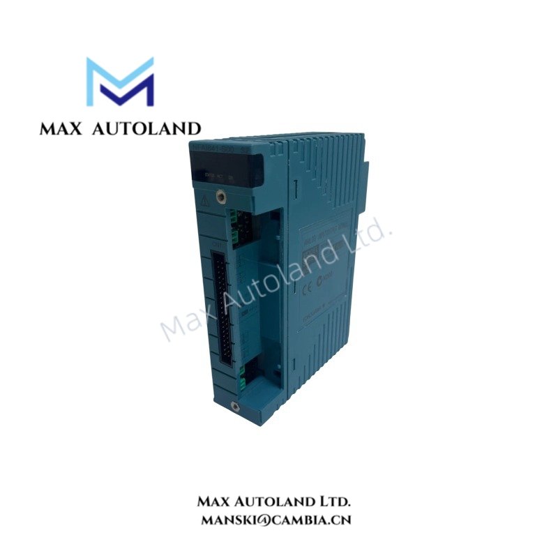
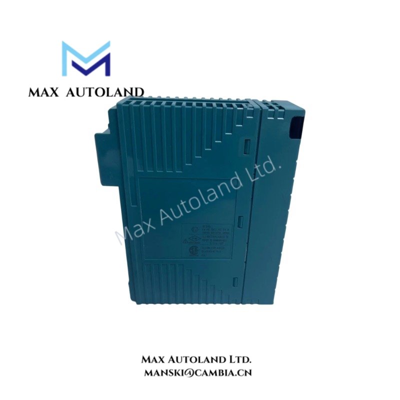
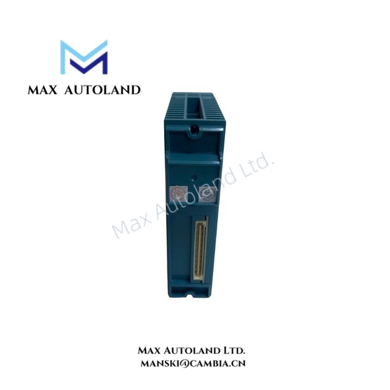
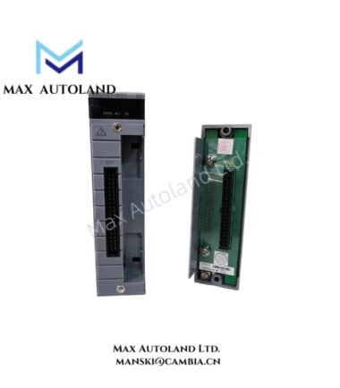
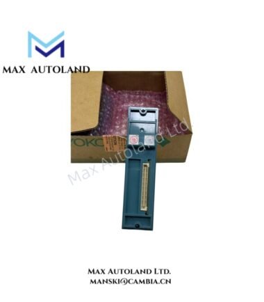
Overview
Hardware Specifications
| Parameter | Specification |
|---|---|
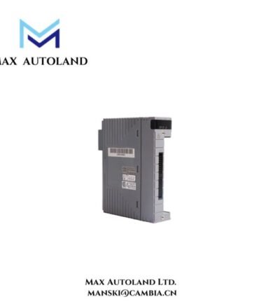
| Model | NFIA841-S50 |
| Brand | Yokogawa |
| Product Type | Analog I/O Module |
| Module Function | 8-channel input / 8-channel output |
| Input Signal | 4-20 mA |
| Output Signal | 4-20 mA |
| Isolation | Non-isolated |
| Input Resistance, Power ON | 250 ohm |
| Input Resistance, Power OFF | 500 kohm or more |
| Allowable Input Current | 25 mA |
| Output Load Resistance | 0 to 750 ohm |
| Input Accuracy | +/- 0.1% of full scale |
| Output Accuracy | +/- 0.3% of full scale |
| Data Refresh Cycle | 10 ms |
| Input Step Response Time | 100 ms |
| Output Step Response Time | 40 ms |
| Transmitter Power Supply | 22.8 to 28.4 V |
| Transmitter Output Current Limit | 27 mA |
| Transmitter Configuration | 2-wire or 4-wire, selected per channel |
| Temperature Drift | Maximum +/- 0.01% per deg C |
Analog Loop Signal Handling
The NFIA841-S50 processes current signals through non-isolated analog input and output circuits. Each input channel accepts a 4-20 mA signal, while each output channel supplies a 4-20 mA control signal.
The module provides overcurrent protection on the input circuit. Its input resistance is 250 ohm when powered and at least 500 kohm when power is off. Output circuits support load resistance from 0 to 750 ohm.
The 10 ms data refresh cycle, 100 ms input step response, and 40 ms output step response define separate signal-processing characteristics. These values should be considered when evaluating loop response and control-system timing.
Because the module is non-isolated, verify the field wiring, grounding arrangement, and electrical potential differences between connected devices before installation.
Frequently Asked Questions
Q: What signals does the NFIA841-S50 support?
A: It supports 4-20 mA analog input and output signals, with eight input channels and eight output channels.
Q: What is the maximum supported output load resistance?
A: The specified output load resistance is 750 ohm.
Q: Can the NFIA841-S50 replace the discontinued NFIA841-S00 directly?
A: The supplied information identifies the NFIA841-S50 as the replacement. Before substitution, verify the complete suffix code, terminal block, connector arrangement, system compatibility, and configuration requirements against the installed hardware and applicable Yokogawa documentation.
Field Installation Guidelines
- Confirm the complete module designation and suffix code before installation.
- Verify the control-system slot assignment and hardware compatibility using the applicable Yokogawa system documentation.
- Check that field transmitters and receiving devices use compatible 4-20 mA signal ranges.
- Configure each channel for the appropriate 2-wire or 4-wire transmitter arrangement.
- Keep analog signal wiring separate from high-voltage and high-current power wiring where practical.
- Apply the control system’s specified shield termination and grounding practices to limit electrical interference.
- Check output load resistance against the specified 0 to 750 ohm range.
- Verify transmitter supply voltage and wiring polarity before energizing the module.
- Do not assume hot-swap capability or channel-to-channel galvanic isolation without confirmation from the applicable hardware manual.
YOKOGAWA Top Products
Customers Also Viewed



Reviews
There are no reviews yet.