
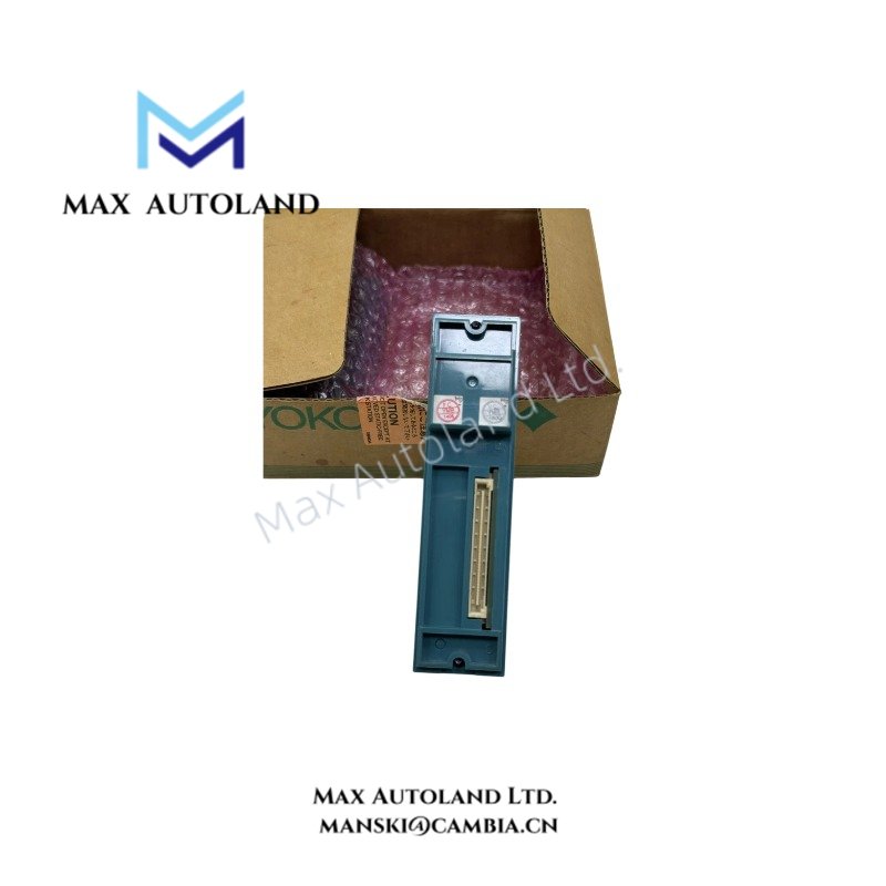
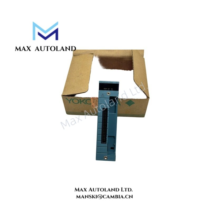

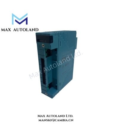
Overview
Suffix Breakdown & Model Matrix
| Code | Description |
|---|---|
| NFAR181 | RTD Input Module base model |
| -S | Standard type |
| 5 | Without explosion protection |
| E | With explosion protection |
| 0 | Basic type |
| 1 | ISA Standard G3 option |
| 4 | Extended temperature range, -40 to +70 deg C |
| 5 | Extended temperature range, -40 to +70 deg C, and ISA Standard G3 option |
| /R8500 | Pressure clamp terminal block for RTD, model NFTR8S-00 |
| /R8510 | Pressure clamp terminal block with surge absorber for RTD, model NFTR8S-10 |
Note: The suffix and option codes are reproduced from the supplied documentation. Confirm the complete ordering code and compatibility before selecting a replacement.
Hardware Specifications
| Parameter | Specification |
|---|---|
| Model | NFAR181-S00 |
| Base Model | NFAR181 |
| Brand | Yokogawa |
| Module Type | RTD Input Module |
| Operating Temp | Standard range not specified; extended option: -40 to +70 deg C |
| Power Consumption | Not specified |
| Input Type | Resistance temperature detector (RTD) |
| Input Channels | 12 isolated channels, as listed for NFAR181 |
| Supported RTD | Pt100, three-wire type; JPt100, three-wire type |
| Measurement Current | 1 mA |
| Data Refresh Cycle | 1 sec |
| Input Resistance | 2 Mohm or more, with power ON or OFF |
| Allowable Signal Source Resistance | Total source and wiring resistance: 1000 ohm or less |
| Wiring Resistance | 40 ohm or less per wire, as listed in the supplied data |
| Withstanding Voltage | 1500 VAC between input and system for 1 minute |
| Reference Junction Compensation Accuracy | Within 1 deg C, where applicable to the configured input type |
| Temperature Drift | Maximum +/-30 ppm/deg C, as listed for the RTD-related specification |
| Environmental Option | ISA Standard G3 available through suffix selection |
| Terminal Block Options | NFTR8S-00 or NFTR8S-10 |
Specification limitation: The supplied table combines data for NFAT141 and NFAR181 and contains OCR errors. Verify each value against the official NFAR181 manual before using it for engineering acceptance or configuration.
RTD Measurement and Input Configuration
The NFAR181 accepts three-wire RTD signals. Correct wiring is required to measure resistance accurately and limit the influence of lead resistance.
- RTD wiring: Confirm the three-wire Pt100 or JPt100 sensor configuration against the module terminal assignments.
- Measurement current: The supplied specification lists 1 mA.
- Input isolation: The model comparison lists NFAR181 as a 12-channel isolated input module.
- Electrical withstand: The listed input-to-system withstand voltage is 1500 VAC for 1 minute.
- Temperature options: The extended-range suffix provides a specified operating range of -40 to +70 deg C.
- Environmental protection: ISA Standard G3 is available through the documented suffix options. Confirm the exact order code on the installed module.
Do not apply thermocouple cold junction compensation requirements to RTD channels unless the configured input type and applicable documentation specifically require them.
Frequently Asked Questions
Q: How many RTD input channels does the NFAR181 support?
A: The supplied comparison table lists 12 isolated input channels for the NFAR181. The 16-channel specification belongs to the NFAT141 entry and should not be applied to the NFAR181.
Q: What RTD sensor types are listed for this module?
A: The supplied specifications identify three-wire Pt100 and JPt100 RTD inputs. Verify the supported sensor configuration and wiring assignments in the applicable hardware manual.
Q: What is the specified data refresh cycle?
A: The supplied data lists a 1-second refresh cycle. Confirm the parameter against the NFAR181-specific documentation before using it for control-loop timing calculations.
Field Installation Guidelines
- Verify the model: Check the complete model and suffix codes against the installed module label and system documentation.
- Check the terminal block: Confirm whether the installation uses NFTR8S-00 or NFTR8S-10 and verify the associated wiring arrangement.
- Connect RTD leads: Follow the manufacturer’s three-wire RTD terminal diagram. Keep sensor wiring separate from high-voltage and high-current conductors.
- Manage shielding: Apply the grounding and shielding arrangement specified by the control-system installation manual. Avoid creating unintended ground loops.
- Check environmental conditions: Confirm that the selected suffix supports the actual ambient temperature and required environmental protection.
- Validate input readings: Compare configured channel readings with a known RTD simulator or calibrated sensor under the approved commissioning procedure.
- Observe electrical limits: Confirm signal-source resistance and wiring resistance against the applicable module specifications.
- Confirm system compatibility: Check module configuration, terminal-block compatibility, and replacement requirements before removing or installing hardware.
YOKOGAWA Top Products
Customers Also Viewed




Reviews
There are no reviews yet.