
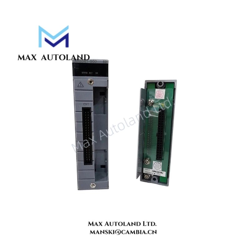
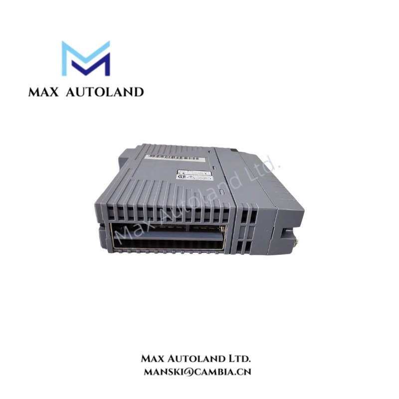
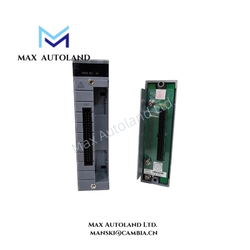
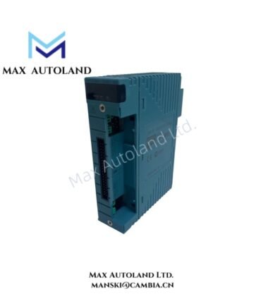
Overview
Hardware Specifications
| Parameter | Specification |
|---|---|
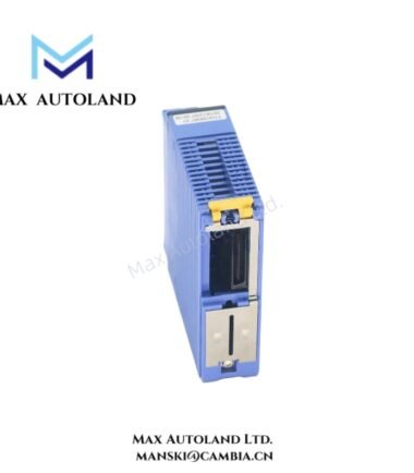
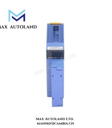
| Model | NFAI841-S00/A4S00 |
| Brand | Yokogawa |
| Product Type | Analog I/O Module |
| System | STARDOM, as specified in the supplied description |
| Module Style | Style S2, as specified in the supplied description |
| Input Channels | 8 |
| Output Channels | 8 |
| Analog Input Signal | 4-20 mA DC, as specified |
| Analog Output Signal | 4-20 mA DC, as specified |
| Data Update Period | 10 ms, as specified |
| Output Load Resistance | 0-750 ohms, as specified |
Analog Signal Interface and Loop Considerations
The specified 4-20 mA signal range supports analog process signal interfacing. However, the input and output electrical specifications should be checked independently before connecting field devices.
- Input loops: Confirm the input circuit type, loop power requirements, common reference arrangement, and permissible input impedance.
- Output loops: Verify the connected device’s input impedance and ensure the total loop resistance remains within the documented output load limit.
- Grounding: The supplied description identifies a non-isolated configuration. Confirm the common-ground arrangement and grounding requirements before wiring multiple channels.
- Signal cabling: Route analog signal cables separately from high-current conductors and switching circuits where practical. Apply the manufacturer’s shield termination instructions.
The supplied information does not establish HART support, channel-to-channel isolation ratings, or compatibility with other fieldbus protocols. Do not assume these features without the relevant hardware manual.
Frequently Asked Questions
Q: Can the module handle analog inputs and outputs simultaneously?
A: The supplied description specifies 8 input channels and 8 output channels. Confirm simultaneous operation and channel allocation in the applicable hardware documentation.
Q: What output load resistance is specified?
A: The supplied data lists 0-750 ohms. Verify the permitted load range and output compliance voltage in the manufacturer’s documentation before commissioning.
Q: Is the module galvanically isolated?
A: The supplied description identifies a non-isolated, common-ground configuration. Confirm the actual isolation boundaries and grounding requirements for the specific hardware revision.
Field Installation Guidelines
- Verify the complete model designation, suffix configuration, and terminal assignment against the manufacturer’s hardware manual.
- Isolate power before installing the module or changing field wiring.
- Identify the positive and return conductors for each analog input and output loop before termination.
- Confirm the common-ground arrangement to avoid unintended current paths between channels or external devices.
- Separate analog signal wiring from motor cables, contactor wiring, and other sources of electrical interference.
- Terminate cable shields according to the manufacturer’s grounding instructions. Avoid creating unintended ground loops.
- Check field-loop continuity, polarity, and connected load resistance before applying power.
- Commission input and output channels individually, then verify signal scaling and controller readings against calibrated test equipment.
YOKOGAWA Top Products
Customers Also Viewed




Reviews
There are no reviews yet.