
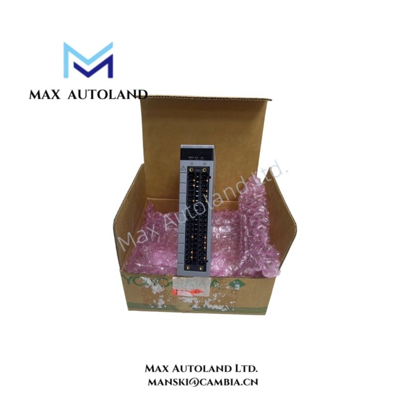
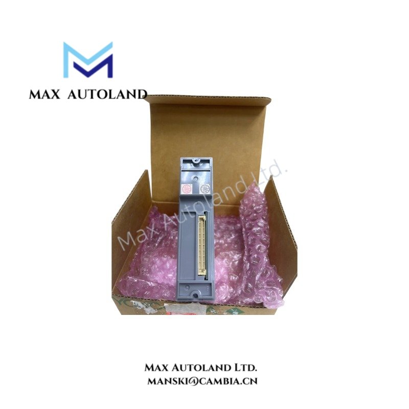
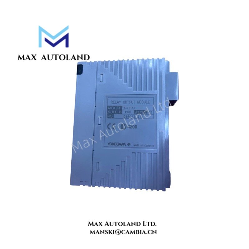
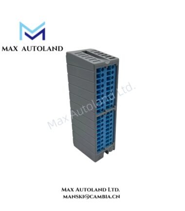
Overview
Hardware Specifications
| Parameter | Specification |
|---|---|
| Model | ADR541-P00 |
| Base Model | ADR541 |
| Brand | Yokogawa |
| Product Type | 16-Channel Isolated Relay Output Module |
| Series | FIO |
| Compatible Systems | CENTUM VP, CENTUM CS 3000 |
| Number of Output Channels | 16 |
| Output Isolation | Isolated relay outputs |
| Terminal Configuration | Common negative terminals grouped by 8 channels |
| Rated Applied Voltage | 24 to 110 VDC |
| AC Applied Voltage | 100 to 240 VAC, 50/60 Hz |
| Resistive Load Current | 2.0 A/channel at 24 VDC and 100/220 VAC |
| Resistive Load Current | 0.4 A/channel at 110 VDC |
| Inductive Load Current | 0.6 A/channel at 24 VDC |
| Inductive Load Current | 0.1 A/channel at 110 VDC |
| Inductive Load Current | 1.0 A/channel at 100/220 VAC |
| Output Functions | ON/OFF status, one-shot pulse-width, time-proportioning |
| Status Output Response Time | 12 ms maximum |
| Mixed Status and Pulse Response Time | 20 ms maximum |
| Pulse Width Range | 40 ms to 7200 s |
| Pulse Width Resolution | 8 ms |
| Power Consumption | 780 mA maximum at 5 VDC |
| Dielectric Withstand Voltage | 2 kVAC for 1 minute, output signal to system |
| Inter-Group Withstand Voltage | 1.35 kVAC for 1 minute |
| Mechanical Switching Life | 100,000 operations minimum |
| External Connection | Dedicated AKB334 cable / pressure-clamp terminal |
| Weight | Approximately 0.3 kg |
| Origin | Japan |
| Tariff Code | 8537101190 |
Relay Contact Switching and Channel Isolation
The ADR541-P00 uses mechanical relay contacts to switch external field loads. Each output channel provides discrete ON/OFF control, while the module also supports one-shot pulse-width and time-proportioning operations.
The 16 output channels use isolated relay circuits with common negative terminals arranged in 8-channel groups. Therefore, field wiring must follow the applicable group-terminal configuration.
The specified switching characteristics include:
- Status output response: 12 ms maximum.
- Mixed status and pulse output response: 20 ms maximum.
- Pulse duration: 40 ms to 7200 s.
- Pulse resolution: 8 ms.
- Minimum mechanical switching life: 100,000 operations.
These values define the specified output response and mechanical switching characteristics. Actual contact life depends on the connected load and switching conditions.
Frequently Asked Questions (FAQ)
Q: What types of field devices can the ADR541-P00 control?
A: The relay outputs can switch compatible AC or DC field loads, including solenoid valves, motor contactors, alarm horns, and indicator lights. However, the connected load must remain within the specified resistive or inductive current ratings.
Q: What is the maximum backplane current consumption?
A: The module consumes a maximum of 780 mA from the 5 VDC backplane supply.
Q: Does the ADR541-P00 support pulse-width output?
A: Yes. The module supports one-shot pulse-width output from 40 ms to 7200 s, with an 8 ms resolution. It also supports continuous status switching and time-proportioning output.
Field Installation Guidelines
1. Module Installation: Install the ADR541-P00 in its designated Yokogawa FIO system position. Confirm mechanical seating and connector engagement before energizing the system.
2. Field Wiring: Use the specified AKB334 dedicated cable or compatible pressure-clamp terminal arrangement. Follow the terminal assignments and 8-channel common-negative grouping.
3. Load Verification: Check the connected load voltage and current before commissioning. Select the applicable resistive or inductive rating according to the field-device characteristics.
4. AC/DC Separation: Route AC and DC field wiring according to the cabinet wiring plan. Maintain appropriate separation between power circuits and low-level signal wiring.
5. Grounding and Shielding: Terminate cable shields according to the system grounding design. Avoid unintended connections between isolated output circuits and cabinet ground.
6. Electrical Testing: Verify relay contact operation, field-device response, and output-state indication during commissioning. Confirm that the applied voltage and load current remain within the specified limits.
7. Maintenance: Isolate the relevant field power circuit before disconnecting wiring or replacing the module. Inspect relay operation and terminal connections during scheduled maintenance.
YOKOGAWA Top Products
| CPU | Power Supply and Battery | Rack |
| SCP451-51 | S9562FA | A1BD5D-06 |
| CP461-10 S1 | S9564FA | A1BR4D-05 |
| CP330D S3 | S9345FA | AKB337-M020 |
| CP461-50 S2 | S9548FA | NFBU200-015 |
| SCP451-53 | S9260DE-01 | NFBU200-S10 |
| SCP401-11 | S9971DB-0 | SNT411-13 |
| S2CP471-01 | S9681DB | SED2D-01 |
| CP451-51 | S9841DA | NFAF135-S00 |
| CP471-01 | SPW484-53 | NFAI835-S50 |
| CP461-53 | NFPW442-50 | NFAI543-H00 |
Customers Also Viewed
| Bently Nevada | ABB | GE Fanuc | Honeywell | Invensys |
|---|---|---|---|---|
| 330101-00-40-05-02-00 | PM591-2ETH | IS200ECTBG2A | CC-TDIL11 | FBM223 |
| 330101-00-40-10-02-00 | PM595-4ETH-F | IS200EPCTG1AZZ | CC-IP0101 | FBM207b |
| 330101-00-40-10-02-05 | DX522 | IS200VRTDH1DAA | CC-PAIX01 | FBM206 |
| 330101-00-43-15-02-05 | AX521 | IS200ERIOH1ACB | CC-TCNT01 | FBM237 |
| 330101-00-52-15-02-05 | AX522 | IS200ERQCH1A | CC-TAOX01 | FBM217 |
| 330101-00-55-05-02-05 | DI524 | IS200EACFG1BAA | CC-PDIS01 | FBM215 |
| 330101-00-55-10-02-05 | DI561 | IS200TVIBH2B | CC-PAIX01 | FBM211 |
| 330101-00-67-10-12-CN | DI562 | IS415UCVGH1A | CC-PAIH01 | FBM207 |
| 330101-00-75-15-02-05 | DI571 | IS200JPDDG1AAA | CC-PUIO31 | FBM223 |
| 330101-00-79-15-02-05 | DI581-S | IS200SPROH1ADD | CC-TAIX51 | FBM231 |


Reviews
There are no reviews yet.