
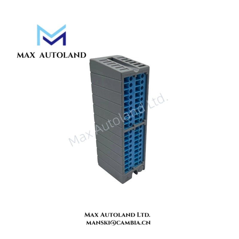
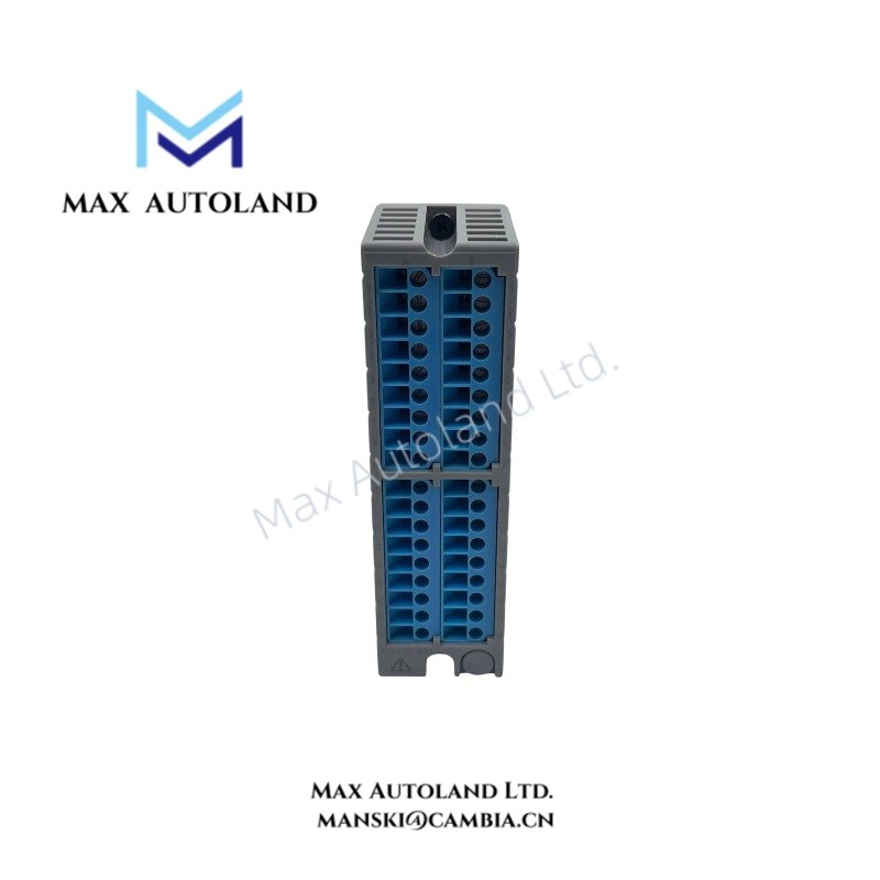
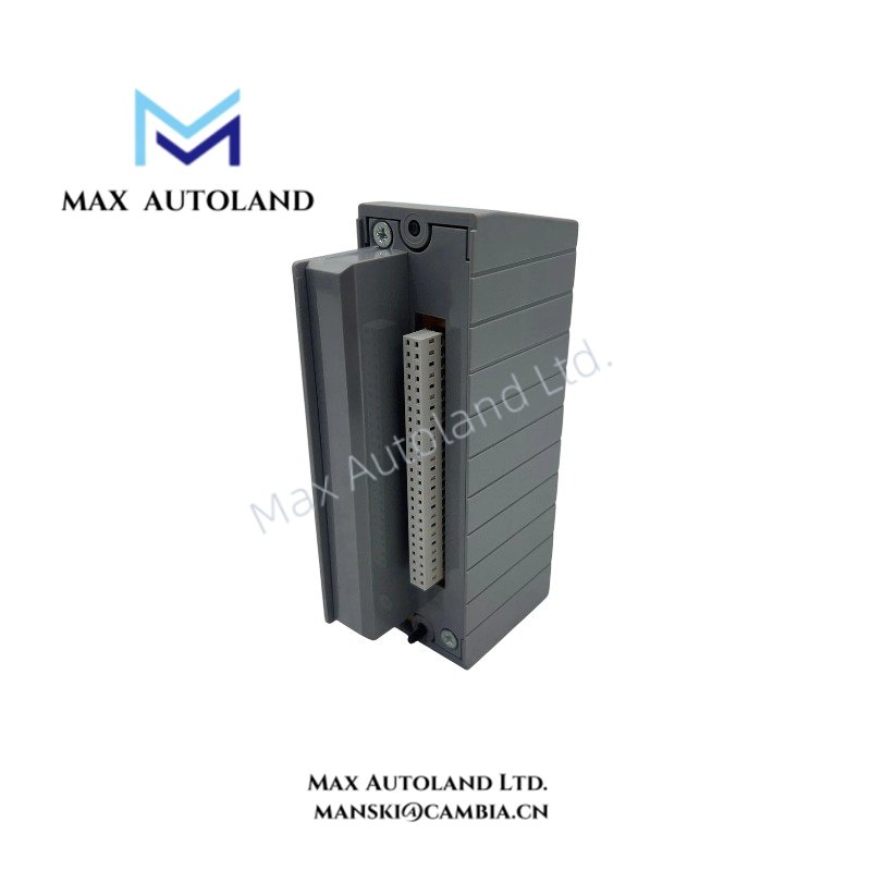
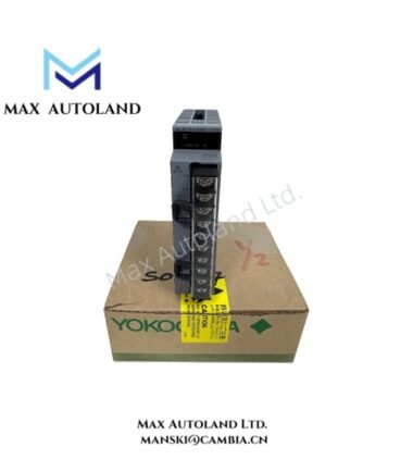
Overview
Hardware Specifications
| Parameter | Specification |
|---|---|
| Model | ATSR3S-0 |
| Brand | Yokogawa |
| Product Type | Pressure Clamp Terminal Block |
| Application | RTD and POT Signal Connections |
| Signal Type | Analog Resistance Temperature Detector (RTD) and Potentiometer (POT) |
| Connection Technology | Pressure Clamp |
| System Compatibility | CENTUM CS, CENTUM VP, CENTUM XL, micro XL, FA-M3, ProSafe-PLC |
| Weight | Approx. 0.2 kg |
| Dimensions | Approx. 3.2 x 11.2 x 6.0 cm |
| Operating Temp | -20 to +70 deg C |
| Wiring Interface | Pressure Clamp Terminals |
| Primary Function | Field Signal Termination |
RTD and Potentiometer Signal Termination
The ATSR3S-0 provides a pressure clamp connection interface for analog RTD and POT signals. Consequently, the terminal block supports physical wiring between field instruments and compatible Yokogawa control system interfaces.
The pressure clamp mechanism secures conductors at the termination points. However, the supplied specifications do not identify conductor size limits, terminal count, or allowable connection current.
For RTD applications, maintain the field wiring configuration specified by the associated input module. Likewise, verify the potentiometer connection arrangement against the applicable system wiring documentation.
Frequently Asked Questions
Q: Which signal types does the ATSR3S-0 support?
A: The ATSR3S-0 is specified for analog RTD and potentiometer (POT) signal connections.
Q: Which Yokogawa platforms are listed as compatible?
A: The listed platforms include CENTUM CS, CENTUM VP, CENTUM XL, micro XL, FA-M3, and ProSafe-PLC. Confirm the applicable terminal arrangement against the system hardware documentation.
Q: Does the ATSR3S-0 require an external power supply?
A: The supplied specifications do not identify a power consumption rating or external power requirement. Verify the electrical requirements of the connected input module before installation.
Field Installation Guidelines
- Verify the ATSR3S-0 model and its compatibility with the target Yokogawa system.
- Confirm the terminal assignment against the applicable wiring diagram before connecting field conductors.
- Identify RTD and potentiometer signal conductors before termination.
- Secure each conductor using the specified pressure clamp mechanism.
- Route analog signal wiring separately from power conductors and high-interference switching circuits where practical.
- Apply the grounding and cable shielding arrangement specified by the control system documentation.
- Inspect each termination for conductor retention, exposed wire strands, and unintended contact with adjacent terminals.
- Verify signal continuity and input readings after completing the wiring inspection.
YOKOGAWA Top Products
| CPU | Power Supply and Battery | Rack |
| SCP451-51 | S9562FA | A1BD5D-06 |
| CP461-10 S1 | S9564FA | A1BR4D-05 |
| CP330D S3 | S9345FA | AKB337-M020 |
| CP461-50 S2 | S9548FA | NFBU200-015 |
| SCP451-53 | S9260DE-01 | NFBU200-S10 |
| SCP401-11 | S9971DB-0 | SNT411-13 |
| S2CP471-01 | S9681DB | SED2D-01 |
| CP451-51 | S9841DA | NFAF135-S00 |
| CP471-01 | SPW484-53 | NFAI835-S50 |
| CP461-53 | NFPW442-50 | NFAI543-H00 |
Customers Also Viewed
| Bently Nevada | ABB | GE Fanuc | Honeywell | Invensys |
|---|---|---|---|---|
| 330101-00-40-05-02-00 | PM591-2ETH | IS200ECTBG2A | CC-TDIL11 | FBM223 |
| 330101-00-40-10-02-00 | PM595-4ETH-F | IS200EPCTG1AZZ | CC-IP0101 | FBM207b |
| 330101-00-40-10-02-05 | DX522 | IS200VRTDH1DAA | CC-PAIX01 | FBM206 |
| 330101-00-43-15-02-05 | AX521 | IS200ERIOH1ACB | CC-TCNT01 | FBM237 |
| 330101-00-52-15-02-05 | AX522 | IS200ERQCH1A | CC-TAOX01 | FBM217 |
| 330101-00-55-05-02-05 | DI524 | IS200EACFG1BAA | CC-PDIS01 | FBM215 |
| 330101-00-55-10-02-05 | DI561 | IS200TVIBH2B | CC-PAIX01 | FBM211 |
| 330101-00-67-10-12-CN | DI562 | IS415UCVGH1A | CC-PAIH01 | FBM207 |
| 330101-00-75-15-02-05 | DI571 | IS200JPDDG1AAA | CC-PUIO31 | FBM223 |
| 330101-00-79-15-02-05 | DI581-S | IS200SPROH1ADD | CC-TAIX51 | FBM231 |


Reviews
There are no reviews yet.