

Overview
Hardware Specifications
| Parameter | Specification |
|---|---|
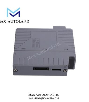
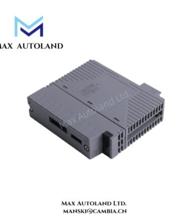
| Model | S2BN1D-19030 |
| Brand | Yokogawa |
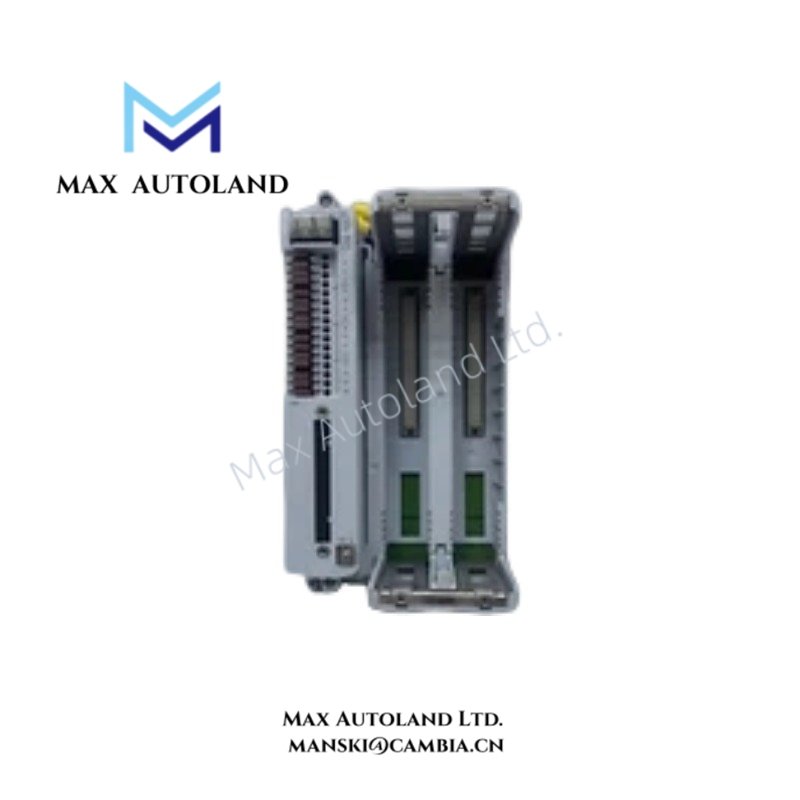
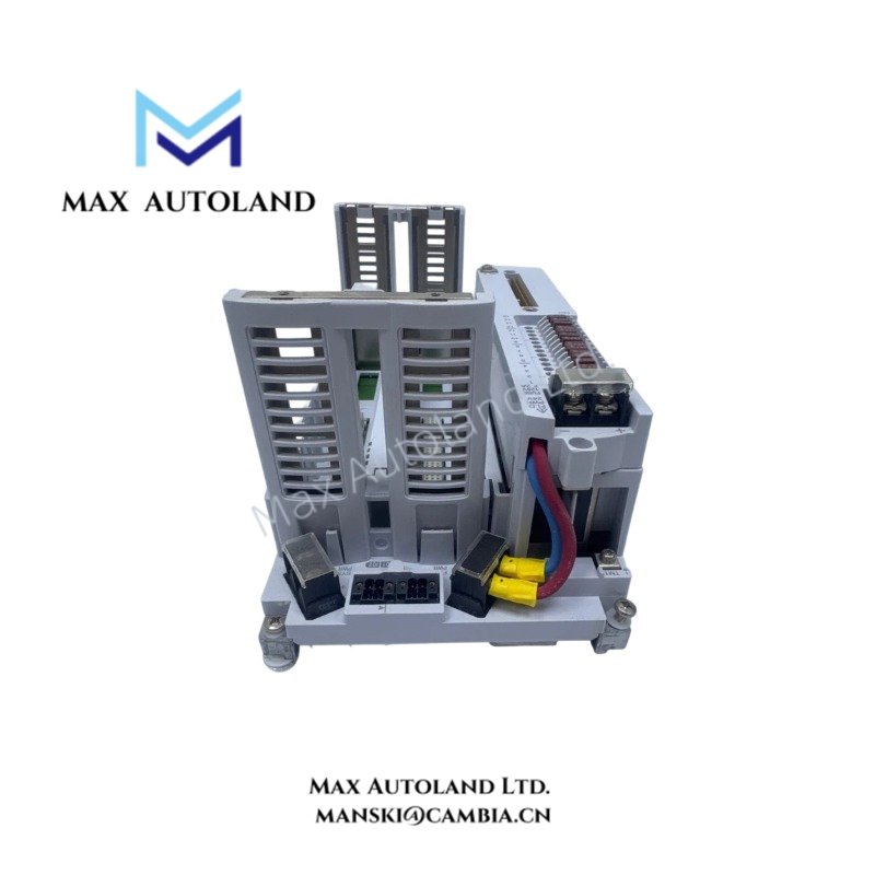
| Product Type | Terminal Base Plate / Interface Unit |
| Weight | Approx. 1.4 kg |
| Operating Temp | -40 to 70 deg C |
| Power Consumption | Not specified |
| Mounting Options | DIN rail mount; wall mount |
| Wall Mounting | M4 x 4 screws |
| I/O Module Configuration | Redundant or single |
| Number of Channels | 16 |
| Bus Connection | F-SB Bus Cable |
| Grounding Terminal | M3 screw terminal |
| Insulation Resistance | 100 Mohm or more at 500 VDC |
F-SB Bus Interface and Electrical Isolation
The S2BN1D-19030 provides physical connection points for F-SB Bus Cable installations. Its terminal base structure supports the mechanical positioning and electrical termination of compatible I/O hardware.
Furthermore, the M3 grounding terminal provides a designated connection point for protective grounding. The specified insulation resistance is at least 100 Mohm when measured at 500 VDC.
The available specifications do not establish channel-to-channel isolation ratings, bus transmission rates, or communication latency. Therefore, verify these parameters against the applicable Yokogawa system documentation before installation.
Frequently Asked Questions (FAQ)
Q: Does the S2BN1D-19030 support redundant I/O configurations?
A: Yes. The specified I/O module configuration supports both redundant and single arrangements. Confirm the applicable system configuration and module compatibility before assembly.
Q: What mounting methods does this terminal base plate support?
A: It supports DIN rail mounting and wall mounting. Wall mounting uses four M4 screws.
Q: What grounding and insulation specifications apply?
A: The unit provides an M3 screw grounding terminal. Its specified insulation resistance is 100 Mohm or more at 500 VDC.
Field Installation Guidelines
- Confirm the terminal base plate model and its compatibility with the intended Yokogawa I/O hardware.
- Select DIN rail or wall mounting according to the cabinet layout.
- For wall mounting, use the specified four M4 screws.
- Connect the F-SB Bus Cable according to the applicable system wiring documentation.
- Connect the grounding conductor to the designated M3 screw terminal.
- Separate field signal wiring from power conductors where practical to reduce electrical interference.
- Verify terminal connections, grounding continuity, and mechanical stability before energizing the system.
- Follow the manufacturer’s installation documentation for wiring assignments, tightening torque, and system-specific electrical requirements.
YOKOGAWA Top Products
| CPU | Power Supply and Battery | Rack |
| SCP451-51 | S9562FA | A1BD5D-06 |
| CP461-10 S1 | S9564FA | A1BR4D-05 |
| CP330D S3 | S9345FA | AKB337-M020 |
| CP461-50 S2 | S9548FA | NFBU200-015 |
| SCP451-53 | S9260DE-01 | NFBU200-S10 |
| SCP401-11 | S9971DB-0 | SNT411-13 |
| S2CP471-01 | S9681DB | SED2D-01 |
| CP451-51 | S9841DA | NFAF135-S00 |
| CP471-01 | SPW484-53 | NFAI835-S50 |
| CP461-53 | NFPW442-50 | NFAI543-H00 |
Customers Also Viewed
| Bently Nevada | ABB | GE Fanuc | Honeywell | Invensys |
|---|---|---|---|---|
| 330101-00-40-05-02-00 | PM591-2ETH | IS200ECTBG2A | CC-TDIL11 | FBM223 |
| 330101-00-40-10-02-00 | PM595-4ETH-F | IS200EPCTG1AZZ | CC-IP0101 | FBM207b |
| 330101-00-40-10-02-05 | DX522 | IS200VRTDH1DAA | CC-PAIX01 | FBM206 |
| 330101-00-43-15-02-05 | AX521 | IS200ERIOH1ACB | CC-TCNT01 | FBM237 |
| 330101-00-52-15-02-05 | AX522 | IS200ERQCH1A | CC-TAOX01 | FBM217 |
| 330101-00-55-05-02-05 | DI524 | IS200EACFG1BAA | CC-PDIS01 | FBM215 |
| 330101-00-55-10-02-05 | DI561 | IS200TVIBH2B | CC-PAIX01 | FBM211 |
| 330101-00-67-10-12-CN | DI562 | IS415UCVGH1A | CC-PAIH01 | FBM207 |
| 330101-00-75-15-02-05 | DI571 | IS200JPDDG1AAA | CC-PUIO31 | FBM223 |
| 330101-00-79-15-02-05 | DI581-S | IS200SPROH1ADD | CC-TAIX51 | FBM231 |




Reviews
There are no reviews yet.