
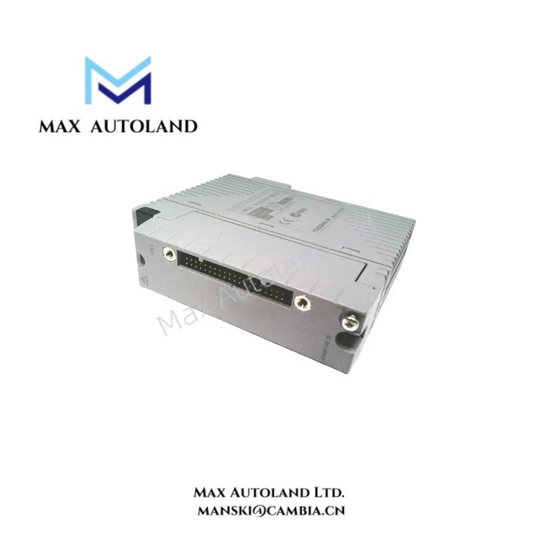
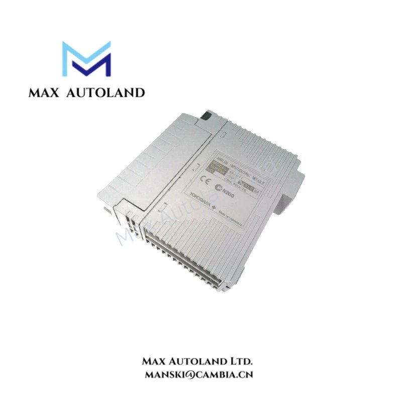
Overview
Hardware Specifications
| Parameter | Specification |
|---|---|
| Model | AAI841-S00 |
| Brand | Yokogawa |
| Product Type | Analog I/O Module |
| Weight | Approx. 0.3 kg |
| Dimensions | Not specified in the provided data |
| Operating Temp | Depends on the selected suffix; -20 to 70 deg C is specified for the temperature option |
| Power Consumption | 5 VDC: 310 mA; 24 VDC: 500 mA maximum current consumption |
| Input Signal | 4-20 mA DC |
| Output Signal | 4-20 mA DC |
| Input Channels | 8 |
| Output Channels | 8 |
| Output Load Resistance | 0 to 750 ohm |
| Input Accuracy | +/-16 uA |
| Output Accuracy | +/-48 uA |
| Data Update Period | 10 ms |
| Transmitter Supply | 14.8 V or higher at 20 mA |
| Temperature Drift | +/-0.1% per 10 deg C |
4-20 mA Loop Interface and HART Configuration
The AAI841 module combines analog signal acquisition and output generation in one module. Its eight input channels receive 4-20 mA signals, while its eight output channels provide corresponding analog control interfaces. The specified standard type is non-isolated, so system designers must evaluate grounding, common-mode voltage, and external loop isolation requirements against the applicable hardware manual.
The -H suffix identifies the variant with HART digital communication. Do not assume HART functionality on the -S standard type. Confirm the complete module suffix and option codes before wiring field devices.
Frequently Asked Questions
Q: How many analog channels does the AAI841 provide?
A: The module provides 8 analog input channels and 8 analog output channels. Both interfaces use 4-20 mA signals according to the supplied specifications.
Q: Does the AAI841-S00 support HART communication?
A: The supplied suffix table identifies -H as the HART-enabled type and -S as the standard type. Confirm the complete order code before connecting HART field instruments.
Q: What power and output load requirements should be checked?
A: The supplied data lists maximum current consumption of 310 mA at 5 VDC and 500 mA at 24 VDC. The specified output load resistance is 0 to 750 ohm. Verify the applicable system power budget and field loop load before commissioning.
Field Installation Guidelines
- Verify the complete model code, suffix codes, and option codes against the installed system documentation before mounting the module.
- Confirm the compatible base unit, rack position, terminal assembly, and cable interface using the applicable Yokogawa hardware manual.
- Check the field transmitter and actuator wiring against the assigned input and output channels.
- Route analog signal wiring separately from high-voltage power cables and sources of electrical interference where practicable.
- Apply shield termination and grounding according to the system grounding design and the manufacturer’s installation instructions.
- Because the specified module configuration is non-isolated, assess loop grounding and potential differences before connecting externally powered instruments.
- Confirm the supply voltage, current budget, output load resistance, and polarity before energizing the circuit.
- For HART applications, verify that the installed module variant supports HART communication and that the field loop meets the requirements of the selected instruments.
- Do not assume hot-swap capability, redundant operation, or explosion-protection approval without checking the exact hardware revision and configuration documentation.
YOKOGAWA Top Products
Customers Also Viewed




Reviews
There are no reviews yet.