
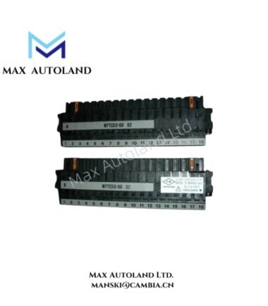
Overview
Suffix Breakdown & Model Matrix
| Parameter | Specification |
|---|---|
| Base Model | SDV541 |
| Original Discontinued Model | SDV541-S33/PRP |
| Replacement Model | SDV541-S63/PRP |
| Suffix -S | Standard type |
| Suffix 5 | For pressure clamp terminal block or MIL cable, without explosion protection |
| Suffix 6 | With signal cable interface adapter, without explosion protection |
| Suffix E | For pressure clamp terminal block or MIL cable, with explosion protection |
| Suffix F | With signal cable interface adapter, with explosion protection |
| Suffix 3 | ISA Standard G3 and temperature range of -20 to 70 deg C |
| Option /B4S00 | Pressure clamp terminal block without surge absorber |
| Option /B4S10 | Pressure clamp terminal block with surge absorber |
| Option /B4D00 | Dual-redundant pressure clamp terminal block without surge absorber |
| Option /B4D10 | Dual-redundant pressure clamp terminal block with surge absorber |
| Option /PRP | Prevention pin for incorrect insertion |
| Option /CCC01 | Connector cover for MIL flat ribbon cable |
| Option /CCC02 | Connector cover for MIL discrete wire cable |
Note: The suffix and option combinations must be checked against the manufacturer’s ordering specifications before selecting a replacement.
Hardware Specifications
| Parameter | Specification |
|---|---|
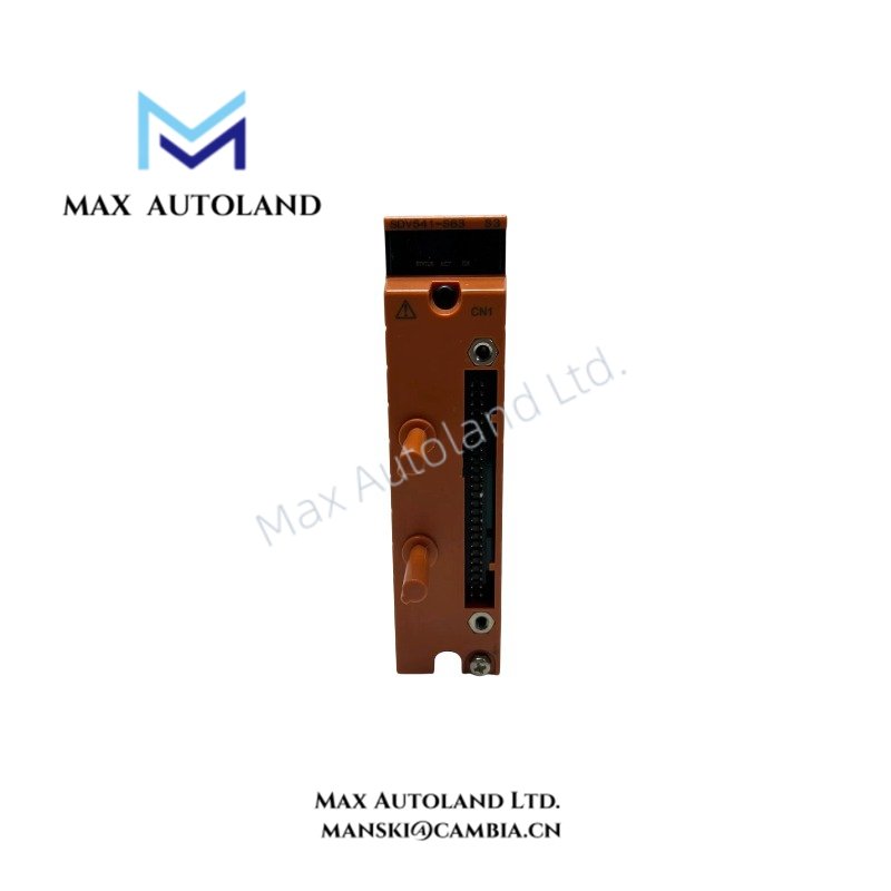
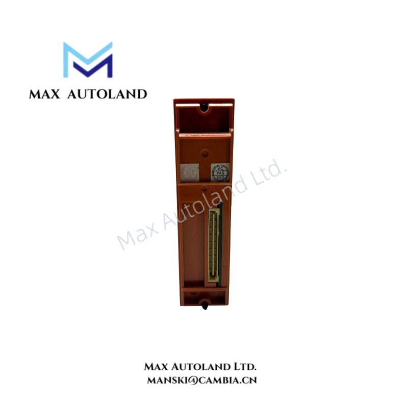
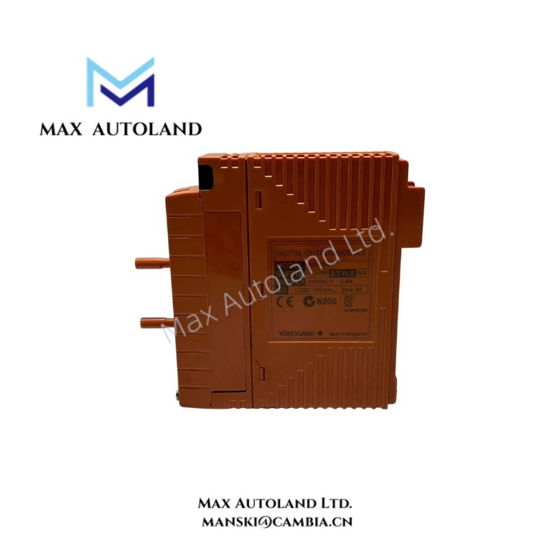
| Model | SDV541-S63/PRP |
| Base Model | SDV541 |
| Brand | Yokogawa |
| Product Type | Digital Output Module |
| System | ProSafe-RS |
| Origin | Not specified in the supplied data |
| Number of Outputs | 16 channels, module isolation |
| Output Voltage | 24 VDC |
| Output Format | Current source |
| Maximum Output Voltage Drop | 1 V |
| External Power Supply | 24 VDC |
| External Supply Tolerance | +20% / -10% |
| Minimum External Supply Current Capacity | 3.4 A |
| Maximum Load Current | 0.2 A per output |
| Maximum Total Output Current | 3.2 A |
| Minimum Load Current | 35 mA |
| Load Resistance Range | 120 to 685 ohm |
| Maximum Off-State Leakage Current | 1.6 mA |
| Maximum Output Response Time | 30 ms |
| Withstand Voltage | 2 kVAC between output signal lines and system, under the specified test connection |
| Maximum 5 VDC Current Consumption | 300 mA |
| Maximum 24 VDC Current Consumption | 150 mA |
| Weight | 0.26 kg for pressure clamp terminal block or MIL cable; 0.31 kg with dedicated signal cable interface adapter |
| Dimensions | Not specified in the supplied data |
| Operating Temp | -20 to 70 deg C for suffix 3; other configurations require confirmation |
| Power Consumption | Up to 1.5 W at 5 VDC and 3.6 W at 24 VDC, calculated from the stated maximum current consumption |
ProSafe-RS Digital Output Characteristics
The SDV541 provides discrete output signals for external loads. Its current-source configuration supplies current to connected field circuits when an output is active. The specified load resistance range is 120 to 685 ohm, with a minimum load current of 35 mA.
The external 24 VDC supply must meet the specified voltage tolerance and current capacity. The maximum off-state leakage current of 1.6 mA should be considered when connecting loads that may respond to small residual currents.
The supplied specifications identify pressure clamp terminals, MIL cable connections, and dedicated signal cable interface adapters as connection options. Surge absorber and dual-redundant terminal block configurations depend on the selected option code.
Frequently Asked Questions
Q: What is the maximum load current per output?
A: Each output supports a maximum load current of 0.2 A. The specified maximum total current across the output lines is 3.2 A.
Q: What external power supply does the SDV541 require?
A: The module uses a 24 VDC external supply with a tolerance of +20% / -10%. The stated minimum current capacity is 3.4 A.
Q: Can the discontinued SDV541-S33/PRP be replaced by the SDV541-S63/PRP?
A: The supplied information identifies SDV541-S63/PRP as the replacement. Before installation, verify the terminal configuration, signal interface, explosion-protection requirements, and system compatibility against the applicable Yokogawa documentation.
Field Installation Guidelines
- Confirm the complete model and suffix codes before installing the module.
- Verify that the external supply provides 24 VDC within the specified tolerance and has sufficient current capacity.
- Check the load resistance and current requirements for every connected output.
- Confirm terminal block or cable interface compatibility with the installed field wiring.
- Route output wiring separately from high-voltage switching and power cables where practical to reduce electrical interference.
- Apply the cabinet and protective grounding arrangements specified by the system installation manual.
- Verify field wiring polarity and terminal assignments before energizing the output circuits.
- For replacement work, confirm the approved shutdown, isolation, and commissioning procedures for the ProSafe-RS system. Do not assume hot-swap support without documentation for the installed configuration.
YOKOGAWA Top Products
Customers Also Viewed





Reviews
There are no reviews yet.