
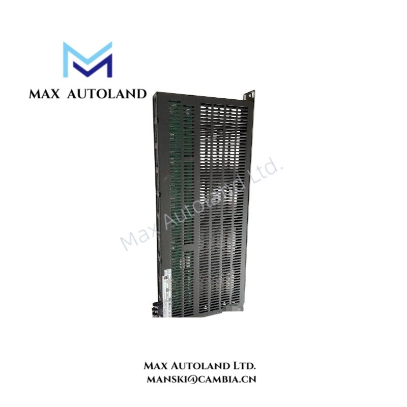
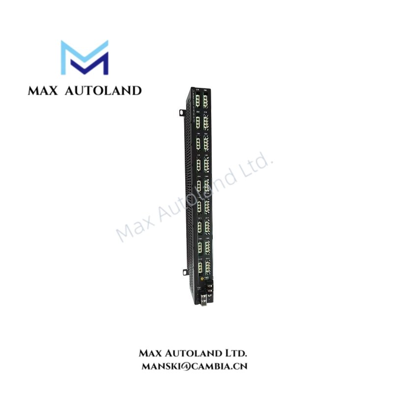
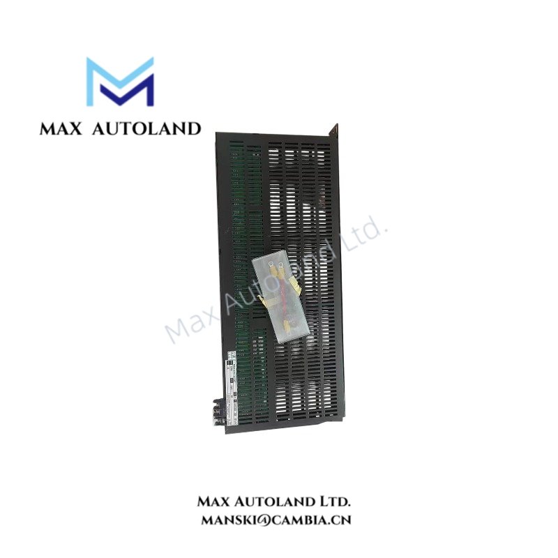
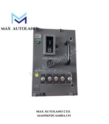
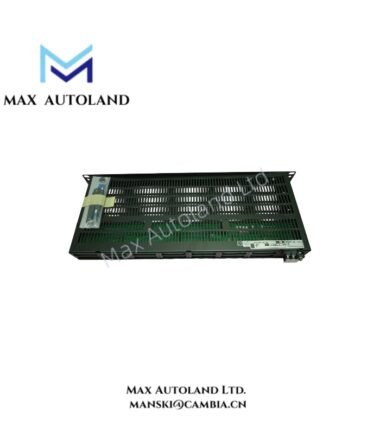
Overview
Hardware Specifications
| Parameter | Specification |
|---|---|
| Model | AEP7D-25 |
| Brand | Yokogawa |
| Product Type | Primary Power Supply Bus Unit |
| Origin | Japan |
| Power Consumption | Passive power distribution |
| Input Voltage | 100 to 120 V AC, 220 to 240 V AC, or 24 V DC |
| Maximum Input Current | 20 A for AC input versions; 30 A for 24 V DC input version |
| Maximum Current per Port | 6 A for AC input versions; 10 A for 24 V DC input version |
| Number of Input Sources | 2 independent inputs, A and B |
| Number of Output Ports | 7 outputs per input; 14 outputs when inputs are connected in parallel |
| Withstanding Voltage | 1500 V AC for AC input versions; 500 V AC for 24 V DC input version |
| Application | Cabinet-level power distribution |
| Hazardous Area / Environmental Options | Depends on suffix code |
Yokogawa Power Distribution Architecture
The AEP7D-25 uses separate A and B input paths to distribute power through their corresponding output ports. This arrangement supports connections to two independent power sources.
When both inputs are connected in parallel, one source can feed all 14 outputs. However, the total input current and individual port current must remain within the applicable ratings. Parallel input wiring does not increase the unit’s rated current capacity.
The specified withstanding voltage is 1500 V AC for AC input models and 500 V AC for the 24 V DC input model. These are dielectric withstand ratings, not operating voltages.
Frequently Asked Questions
Q: How many output ports does the AEP7D-25 provide?
A: It provides seven output ports corresponding to input A and seven corresponding to input B. Connecting the two inputs in parallel allows one source to feed 14 output ports.
Q: What are the maximum input and output current ratings?
A: The AC input versions have a maximum input current of 20 A and a maximum port current of 6 A. The 24 V DC input version has a maximum input current of 30 A and a maximum port current of 10 A.
Q: Does the AEP7D-25 support hazardous-area installation?
A: The available suffix codes include versions with and without explosion protection. Confirm the complete model code and its applicable certification before installation in a hazardous area.
Field Installation Guidelines
- Verify the complete model and suffix code against the required input voltage and environmental classification.
- Connect input A and input B according to the manufacturer’s wiring diagram. Maintain separation between independent sources unless the approved configuration specifically permits parallel connection.
- Check the total input current and each output port current against the ratings for the selected voltage version.
- Use appropriately rated conductors, terminals, overcurrent protection, and cabinet grounding in accordance with the manufacturer’s instructions and applicable electrical standards.
- Keep power wiring organized and separated from low-level analog and communication signal wiring where required by the installation design.
- Confirm terminal tightness, polarity for DC connections, and input voltage before energizing the unit.
- Do not assume hot-swap capability or automatic source transfer. Verify these functions in the applicable Yokogawa hardware documentation before performing maintenance.
YOKOGAWA Top Products
Customers Also Viewed


Reviews
There are no reviews yet.