


Overview
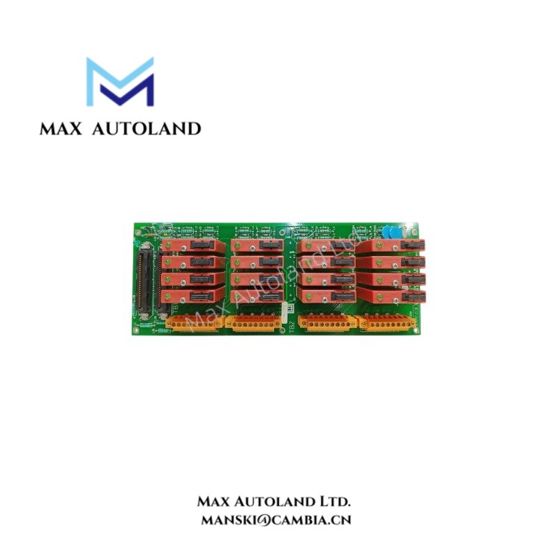
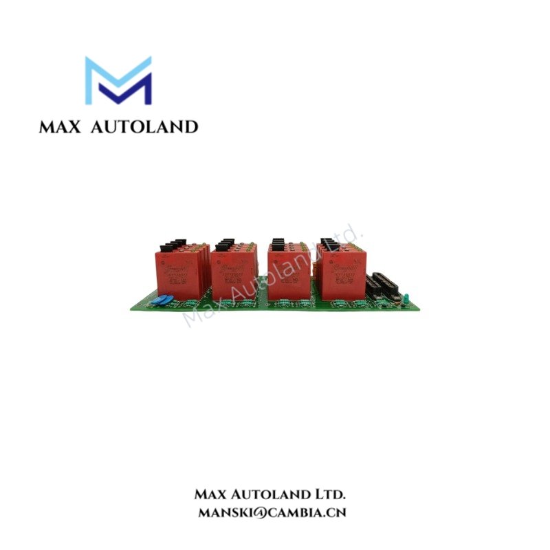
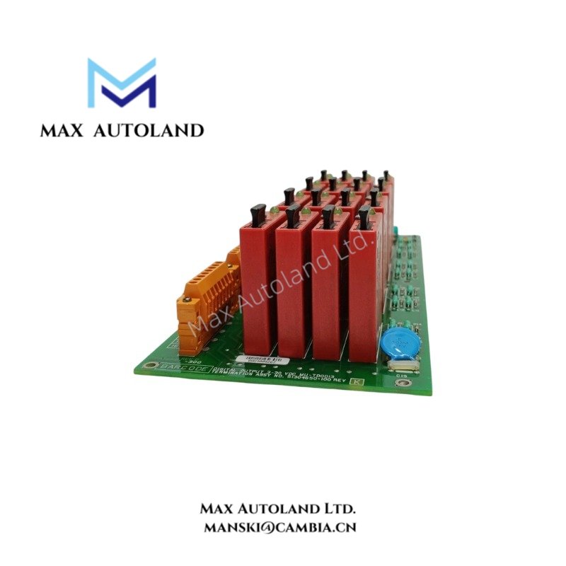
The Honeywell MU-TDOD13 are Field Termination Assemblies (FTAs) for 16-point digital output configurations. Each output uses a normally open power transistor switch, with separate emitter and collector terminals available for connection. The assemblies support independent output loads and separate load power supplies, with voltage ranges and electrical characteristics varying by model.
Technical Specifications
| Parameter | Specification |
|---|---|
| Product Type | Digital Output 16-Point Field Termination Assembly |
| Brand | Honeywell |
| Model Numbers | MU-TDOD13 |
| Output Channels | 16 |
| Output Terminals | Emitter and collector terminals available |
| Load Voltage Range | 3-30 VDC |
| Load Voltage Range | 5-30 VDC |
| Maximum Continuous Load Current | 1.25 A DC per output |
| Load Fuse Rating | 2.5 A, 125 V, slow-blow fuse per output |
| Fuse Size | 5 x 20 mm |
| Fuse Type | BUSS GDC-2.5 A |
| Minimum Load Current | 10 mA DC |
| Isolation | 1500 V RMS between field terminals and system power supply common |
| On-State Voltage Drop | 1.6 V maximum at maximum load current |
| On-State Voltage Drop | 3.0 V maximum at maximum load current |
| Off-State Leakage Current | 10 uA DC maximum |
| Off-State Leakage Current | 100 uA DC maximum |
| Turn-On / Turn-Off Time | 1 ms maximum |
| Contact Suppression | Diode clamp (shunt) |
| Surge Withstand Capability | ANSI/IEEE C37.90.1-1978 |
Output Switching and Load Requirements
Each output uses a transistor switch rather than a mechanical relay contact. The available emitter and collector terminals allow the field circuit to be wired according to the required output configuration. Because the outputs operate independently, each load can use a separate power supply, subject to the specified electrical limits.
The load voltage range depends on the FTA model. MU-TDOD13 and MU-TDOD53 support 3-30 VDC, while MU-TDOD14 and MU-TDOD54 support 5-30 VDC. When selecting an assembly, verify the field supply voltage, load current, and on-state voltage drop against the requirements of the connected device.
Protection and Electrical Characteristics
Each output has a replaceable 2.5 A, 125 V slow-blow fuse in a 5 x 20 mm fuseholder. The specified BUSS fuse type is GDC-2.5 A. The maximum continuous load current is 1.25 A per output; the fuse rating does not increase this operating limit.
The assemblies also specify 1500 V RMS isolation between the field terminals and the system power supply common. A diode clamp provides shunt suppression. The maximum turn-on and turn-off time is 1 ms, while the off-state leakage current differs between the two model groups.
Frequently Asked Questions
Q: What is the difference between MU-TDOD13 / MU-TDOD53 and MU-TDOD14 / MU-TDOD54?
A: The specified load voltage ranges, on-state voltage drops, and maximum off-state leakage currents differ. The 13 and 53 models support 3-30 VDC, with a maximum 1.6 V on-state drop and 10 uA leakage. The 14 and 54 models support 5-30 VDC, with a maximum 3.0 V on-state drop and 100 uA leakage.
Q: Can each output use a separate load power supply?
A: Yes. The specifications state that the 16 outputs operate independently and can use independent load power supplies. Confirm the field wiring arrangement and electrical limits before connecting the loads.
Q: What fuse does this assembly require?
A: Each output uses a replaceable 2.5 A, 125 V slow-blow fuse measuring 5 x 20 mm. The specified fuse type is BUSS GDC-2.5 A.


Reviews
There are no reviews yet.