
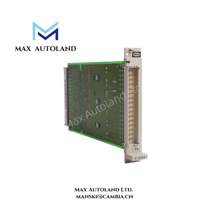
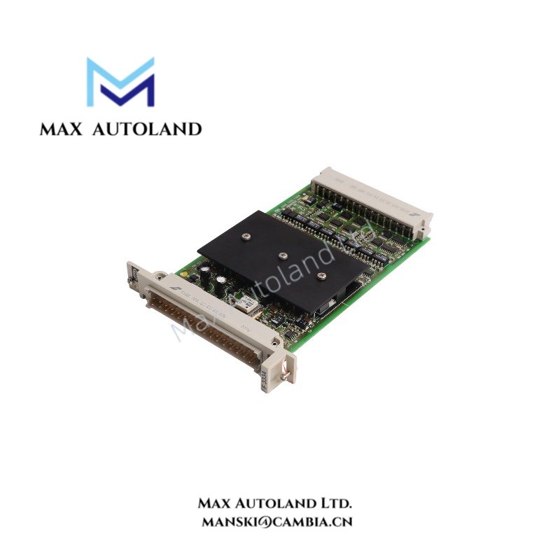
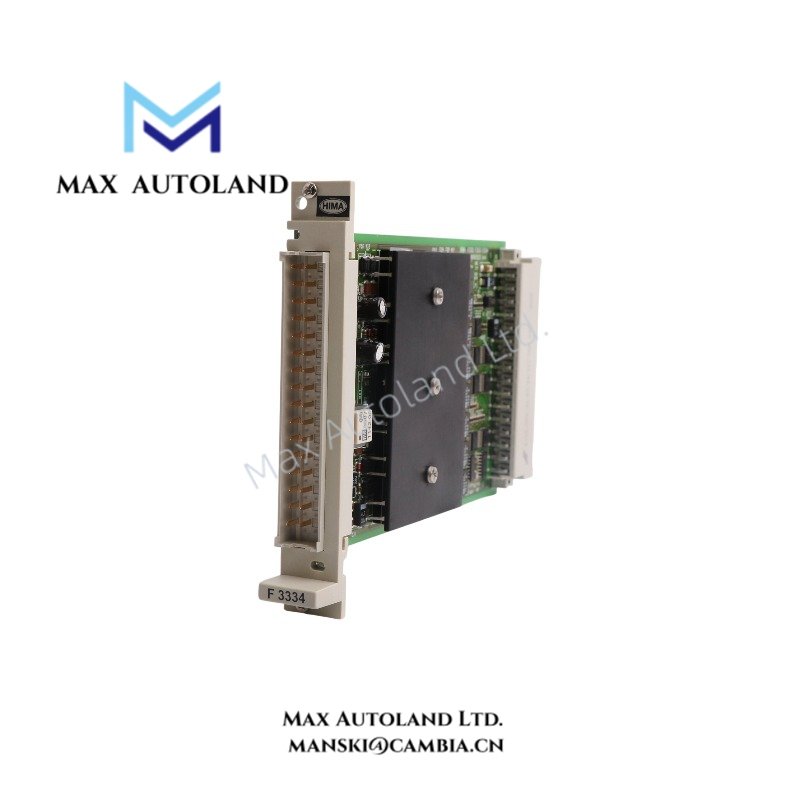
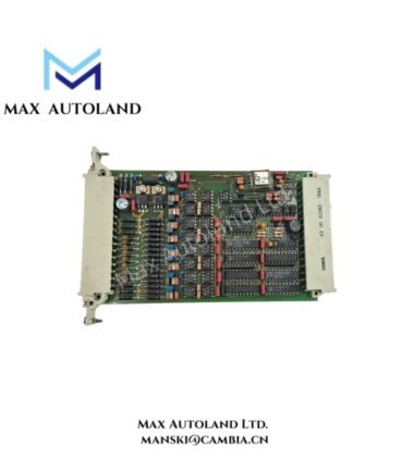
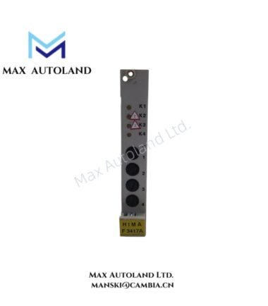
Overview
Hardware Specifications
| Parameter | Specification |
|---|---|
| Model | F3334 |
| Brand | HIMA |
| Product Type | Safety-Related Digital Output Module |
| Number of Outputs | 4 |
| Output Current | Up to 2 A per channel |
| Maximum Load Power | 48 W |
| Lamp Load | Up to 25 W |
| Safety Functions | Integrated safety shutdown |
| Electrical Isolation | Safe isolation |
| Line Monitoring | Supported |
| Short-Circuit Protection | Short-circuit-proof outputs |
| Internal Voltage Drop | Max. 2 V at 2 A load |
| Maximum Line Resistance | 3.6 Ohm |
| Undervoltage Trip | At or below 16 V |
| Short-Circuit Current Operating Point | 2.6-5 A |
| Line-Break Detection Current | 0.5-9.5 mA |
| Maximum Output Leakage Current | 550 uA |
| Maximum Output Voltage in Reset State | 1.5 V |
| Maximum WD Current Input | 30 mA |
| Maximum Test Signal Duration | 250 us |
| Supply Current at 5 VDC | 130 mA |
| Additional Load Supply Current at 24 VDC | 130 mA |
| Rack Space Requirement | 4 TE |
| Estimated Shipping Dimensions | 2.1 x 19 x 12.8 cm |
| Weight | 0.24 kg |
Output Monitoring and Protection
The F3334 automatically tests its output circuits during operation. Its diagnostic routines read back output signals, check switching capability using test signals and a walking-bit test, and monitor field wiring for line breaks. The readback circuit may not detect a fault that raises the zero-signal level to 6.5 V or less, so this threshold matters when evaluating fault-detection behavior.
The module also monitors supply undervoltage and provides short-circuit protection. When the L- supply is interrupted, the module does not provide an output signal. In the reset state, the output voltage remains at a maximum of 1.5 V according to the supplied specifications.
Load Limits and Planning Conditions
The module has specific restrictions for simultaneous operation. Follow these limits when sizing loads and configuring the I/O rack:
- Maximum simultaneous load: Only two channels may operate at 2 A each at the same time. If each channel draws no more than 1 A, all four channels may operate simultaneously.
- Line-break monitoring: The connected load must draw at least 10 mA for line-break monitoring. The supplied documentation limits the use of the “line break” signal in the user program to requirement class AK 3.
- I/O rack capacity: Use no more than 10 output modules with nominal load in one I/O rack.
- Parallel connection: The outputs can be connected in parallel without external diodes, subject to the system design and load requirements.
- Lamp inrush current: Certain 25 W lamp types may produce excessive inrush current. The associated software function block provides an INRUSH CURRENT IN ms setting of 1-50 ms to suppress fault signals during startup. When this setting is active, the test duration can extend to the configured interval.
Frequently Asked Questions
Q: Is the HIMA F3334 an analog or digital output module?
A: The supplied electrical specifications identify it as a four-channel digital output module. Its outputs switch discrete loads rather than generate a continuous analog current or voltage signal.
Q: Can all four channels operate at 2 A simultaneously?
A: No. The stated limit permits two channels to operate at 2 A simultaneously. All four channels may operate together when each load draws no more than 1 A.
Q: What load conditions are required for line-break monitoring?
A: The connected load must draw at least 10 mA. The specified maximum combined outgoing and return line resistance is 3.6 Ohm. Also account for the documented detection-current range of 0.5-9.5 mA when assessing the field circuit.




Reviews
There are no reviews yet.