

Overview
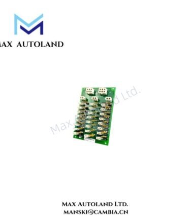
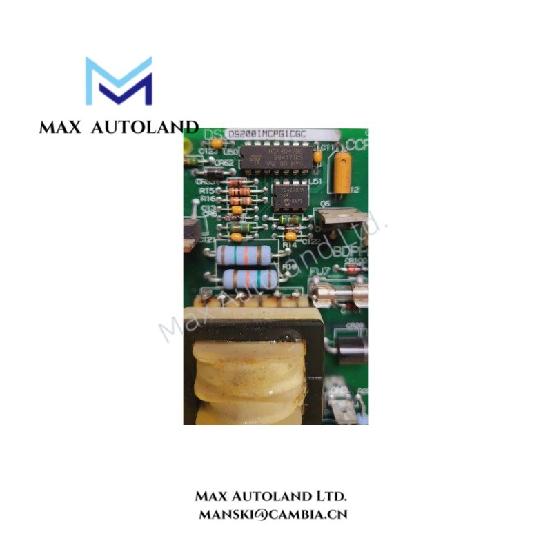
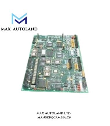
The GE DS200IMCPG1CGC, associated with the DS200IMCPG1C base model designation, serves as an IGBT Power Supply Board in GE drive control equipment. It supports power distribution within the control panel. In addition, the GE Mark V panel power system can accept up to two 120/240 VAC sources and/or one 125 VDC source. Each incoming source requires a dedicated external circuit breaker.
Hardware Specifications
| Parameter | Specification |
|---|---|
| Model | DS200IMCPG1CGC |
| Base Model | DS200IMCPG1C |
| Brand | General Electric (GE) |
| Series | Drive Control / Mark V |
| Product Type | IGBT Power Supply Board |
| Origin | United States (USA) |
| Weight | 0.72 kg |
| Dimensions | 28 x 22 x 3.5 cm |
| Operating Temp | 0 to 60 deg C |
| Panel Power Sources | Up to two 120/240 VAC sources and/or one 125 VDC source |
| External Circuit Protection | Dedicated 30 A, 2-pole thermal-magnetic circuit breaker per input source |
| Internal Power Distribution | Common 125 VDC panel distribution bus |
| Availability | In stock |
Drive Power Distribution and Protection
The GE Mark V panel uses a common 125 VDC bus to distribute DC power within the system. Each core also has its own power supply board, which connects to this distribution arrangement.
Furthermore, the panel supports AC and DC input sources according to the specified configuration. Each incoming source must pass through a dedicated external 30 A, 2-pole thermal-magnetic circuit breaker. This arrangement protects each source and allows technicians to isolate it during maintenance.
The panel diagnostics system monitors power sources and feeder conditions. It also checks the fuses in solenoid circuits on the relay terminal board. As a result, technicians can use these diagnostic functions to identify power distribution faults.
However, the supplied information does not confirm the board’s exact overcurrent thresholds, overvoltage limits, thermal protection settings, or internal fault detection circuits. Consult the applicable GE technical documentation before relying on these functions.
Frequently Asked Questions (FAQ)
Q: Which power sources can the Mark V panel use?
A: The panel can use up to two 120/240 VAC sources and/or one 125 VDC source. In addition, each incoming source requires a dedicated external 30 A, 2-pole thermal-magnetic circuit breaker.
Q: How does the common 125 VDC distribution bus work?
A: The bus distributes DC power within the panel. Each core has an individual power supply board that works within this power distribution arrangement.
Q: Can technicians replace the board while the panel remains energized?
A: The supplied specifications do not confirm hot-swapping support. Therefore, technicians should isolate the relevant power sources, follow the site’s lockout/tagout procedure, and verify electrical isolation before removing the board.
Field Installation Guidelines
- Verify the part number. First, check the complete DS200IMCPG1CGC model and board revision against the equipment bill of materials and GE documentation.
- Isolate all relevant power sources. Before installation, apply the site’s lockout/tagout procedure and verify that the applicable AC and DC supplies are disconnected.
- Inspect the board. Next, check the connectors, mounting points, terminals, and circuit board for visible damage.
- Check the power wiring. Confirm that the incoming power sources, circuit breakers, and 125 VDC distribution bus match the approved panel drawings.
- Route cables correctly. Keep power conductors separate from low-level signal and communication cables where the panel design requires separation. Also, follow the specified grounding and clearance requirements.
- Check the operating temperature. Ensure that the installation environment remains within the specified range of 0 to 60 deg C.
- Complete commissioning checks. Finally, verify the wiring, protective devices, and panel power status according to the applicable GE procedures.