
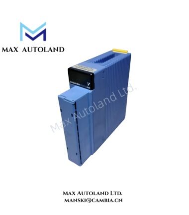
Overview
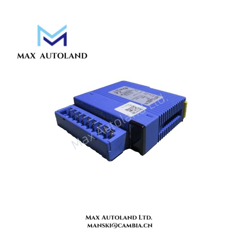
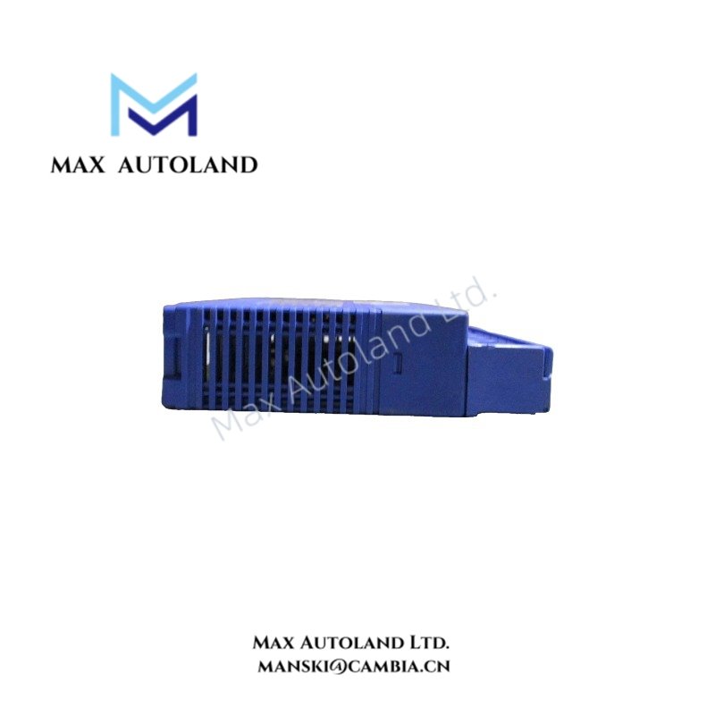
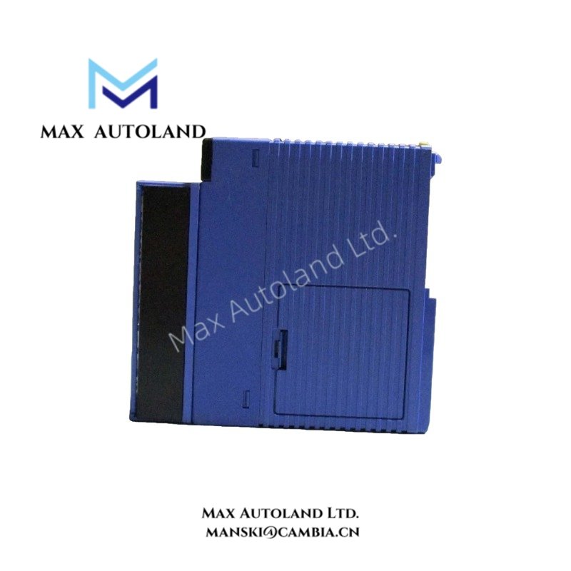
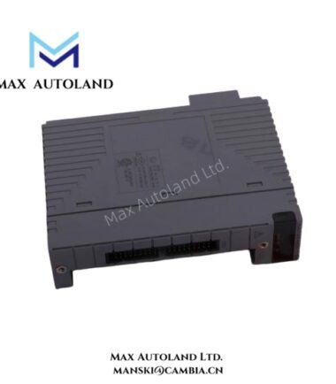
The Yokogawa F3AD08-4W, also identified as the F3AD08-4W analog input module, converts differential voltage or current signals into 12-bit digital values for processing by the FA-M3 PLC. It supports sequential A/D conversion, configurable scaling and offset, per-channel filtering, and peak and trough value recording. The module provides eight differential input channels with photocoupler isolation between the input terminals and internal circuitry.
Hardware Specifications
| Parameter | Specification |
|---|---|
| Model | F3AD08-4W |
| Brand | Yokogawa |
| Product Series | FA-M3 |
| Module Type | Analog Input Module |
| Number of Inputs | 8 differential inputs |
| A/D Conversion Resolution | 12 bit |
| Input Signal Ranges | 0 to 5 VDC, 1 to 5 VDC, -10 to 10 VDC, 0 to 10 VDC, 0 to 20 mA DC, 4 to 20 mA DC |
| Conversion Cycle | 1 ms x number of inputs |
| Conversion Cycle for 8 Inputs | 8 ms |
| Maximum Resolution | 1.4 mV for 0 to 5 VDC, 1 to 5 VDC, or 0 to 10 VDC; 5.7 mV for -10 to 10 VDC; 5.6 uA for current input |
| Overall Accuracy | +/- 0.2% of full scale at 23 +/- 2 deg C; +/- 0.5% of full scale from 0 to 55 deg C |
| Allowable Common-Mode Voltage | +/- 6 VDC for 0 to 5 VDC, 1 to 5 VDC, and current ranges; +/- 1 VDC for -10 to 10 VDC and 0 to 10 VDC |
| Input Resistance | 1 Mohm minimum for voltage input; 250 ohm for current input |
| Absolute Maximum Rating | +18 VDC or +25 mA DC maximum; -18 VDC or -25 mA DC minimum |
| Withstanding Voltage | 500 VDC for 1 minute |
| Scaling | Upper and lower limits configurable from -30,000 to 30,000 |
| Offset Adjustment | -5,000 to 5,000 |
| Filtering | First-order lag filter or moving average |
| Data Recording | Peak and trough values |
| Self-Diagnosis | Hardware self-diagnosis during operation |
| Power Consumption | 210 mA at 5 VDC |
| External Connection | 18-point terminal block, M3.5 screws |
| Dimensions | 28.9 x 100 x 106.1 mm (W x H x D) |
| Weight | 200 g |
| Operating Temperature | 0 to 55 deg C for the stated accuracy specification |
Analog Input Processing and Signal Conversion
The F3AD08-4W accepts differential analog signals and converts them into 12-bit digital values through sequential channel scanning. With eight input channels included in the scan, the specified conversion cycle is 8 ms.
The module supports configurable scaling and offset values for signal representation. Users can enable a first-order lag filter or moving-average calculation for individual channels. Peak and trough recording captures signal extremes, while over-range detection and hardware self-diagnosis support input monitoring.
Photocoupler isolation separates the external input terminals from the internal circuitry. However, the input terminals do not provide channel-to-channel isolation. Field wiring must therefore comply with the specified common-mode voltage limits and input ratings.
Frequently Asked Questions
Q: How many analog input channels does the F3AD08-4W provide?
A: The F3AD08-4W provides eight differential input channels. The stated conversion cycle is 1 ms per input point, resulting in an 8 ms cycle when all eight inputs are scanned.
Q: Which analog signals can the module accept?
A: The supplied family specifications list voltage ranges of 0 to 5 VDC, 1 to 5 VDC, -10 to 10 VDC, and 0 to 10 VDC, along with current ranges of 0 to 20 mA DC and 4 to 20 mA DC. Confirm the applicable ranges for the F3AD08-4W against its model-specific manual before wiring.
Q: Are the eight input channels individually isolated?
A: No. The module uses photocoupler isolation between the input terminals and the internal circuit, but the input terminals are not isolated from one another. Observe the specified common-mode voltage limits when connecting field signals.
Field Installation Guidelines
- Confirm the supported input range and terminal assignment in the F3AD08-4W hardware manual before wiring.
- Check voltage polarity and current loop connections before energizing the system.
- Keep input signals within the specified operating ranges and absolute maximum ratings.
- Observe the common-mode voltage limits when connecting differential signals from separate field devices.
- Route analog signal cables away from high-current conductors and switching circuits to reduce electrical interference.
- Apply cable shielding and grounding according to the control system’s grounding design.
- Secure field wiring to the 18-point terminal block using M3.5 screw connections and the manufacturer’s specified tightening torque.
- Verify the FA-M3 backplane power budget for the stated 210 mA current consumption at 5 VDC.
- After installation, verify input readings, scaling, offset, filter settings, and over-range detection using known signal values.
YOKOGAWA Top Products
Customers Also Viewed




Reviews
There are no reviews yet.