
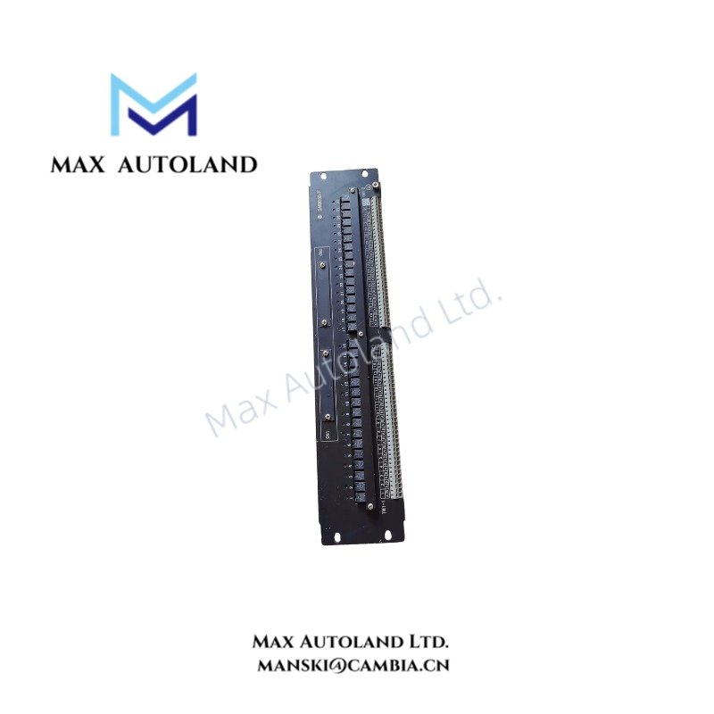
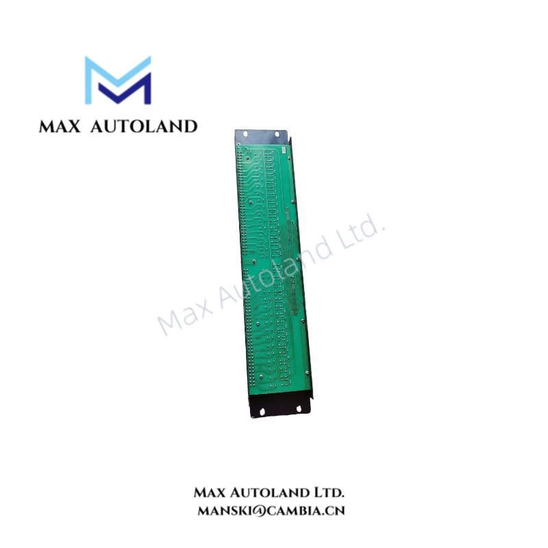
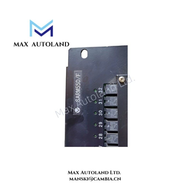
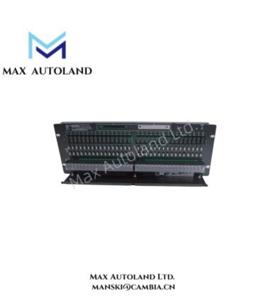
Overview
Hardware Specifications
| Parameter | Specification |
|---|---|
| Model | ARM55D |
| Brand | Yokogawa |
| Product Type | Mechanical Relay Output Board |
| Contact Type | Mechanical relay, dry contact, normally open (NO) |
| Contact Points | 32 points |
| Redundancy | Single or dual redundant |
| Field Terminals | M4 screw terminals |
| Compatible Connection Module | ADV551 (32-point DO) + ATD5A terminal block |
| Alternative Connection Module | ADV561 (64-point DO), subject to configuration compatibility |
| Signal Cables | AKB331 (32-point), AKB337 (64-point) |
| Maximum Load | 250 VAC: 2 A per point; 30 VDC: 2 A per point; 125 VDC: 0.1 A per point |
| Minimum Load | 5 V, 10 mA |
| Power Supply Voltage | 24 VDC |
| Internal Circuit Current Consumption | Maximum 0.65 A; external power supply required |
| Field Device Power Supply | External power supply required |
| Insulation Resistance | At least 10 Mohm at 500 VDC |
| Withstand Voltage | Field terminals to case: 2 kV; 24 V power terminals to case: 500 V; 24 V power terminals to field terminals: 2 kV |
| Operating Temp | 0 to 50 deg C |
| Operating Humidity | 10 to 90% RH |
| Safety Standard | CSA, as specified in the provided data |
| EMC Standards | CE marking and C-Tick marking, as specified in the provided data |
| Dimensions | 482.6 mm W x 132.5 mm H (3U); depth not specified |
| Weight | 2.2 kg |
Relay Contact Switching and Electrical Characteristics
The ARM55D switches field circuits through mechanical relay contacts. Each output uses a normally open contact arrangement. The specified maximum switching loads differ by voltage type: 2 A per point at 250 VAC, 2 A per point at 30 VDC, and 0.1 A per point at 125 VDC.
The connected load must remain within the applicable voltage and current limits. Verify the load’s inrush current and switching characteristics before connecting inductive devices. External suppression may be required for inductive loads, depending on the circuit and applicable installation requirements.
Frequently Asked Questions
Q: What is the maximum output current per contact?
A: The specified maximum is 2 A per point at 250 VAC or 30 VDC, and 0.1 A per point at 125 VDC.
Q: Which connection components are specified for the ARM55D?
A: The listed components are the ADV551 digital output module and ATD5A terminal block for 32-point connections. The ADV561 and AKB337 are listed for 64-point configurations; verify the applicable system configuration before use.
Q: Does the ARM55D require an external power supply?
A: Yes. The internal circuit requires a 24 VDC external supply, with a stated maximum current consumption of 0.65 A. Field device power also requires an external supply.
Field Installation Guidelines
- Confirm the ARM55D model and the intended single or dual-redundant configuration before installation.
- Verify compatibility among the relay board, digital output module, terminal block, and signal cable.
- Secure field wiring using the specified M4 screw terminals and check each connection for mechanical stability.
- Confirm that field voltage, steady-state current, and switching conditions remain within the specified contact ratings.
- Provide the required external 24 VDC supply for the internal circuit. Verify supply polarity and wiring against the manufacturer’s documentation.
- Route field wiring separately from high-noise power conductors where practical. Apply suitable grounding and shielding practices based on the connected equipment and site wiring standards.
- Inspect insulation and wiring clearances before energizing the assembly. Perform appropriate electrical checks in accordance with the system maintenance procedures.
YOKOGAWA Top Products
Customers Also Viewed


Reviews
There are no reviews yet.