
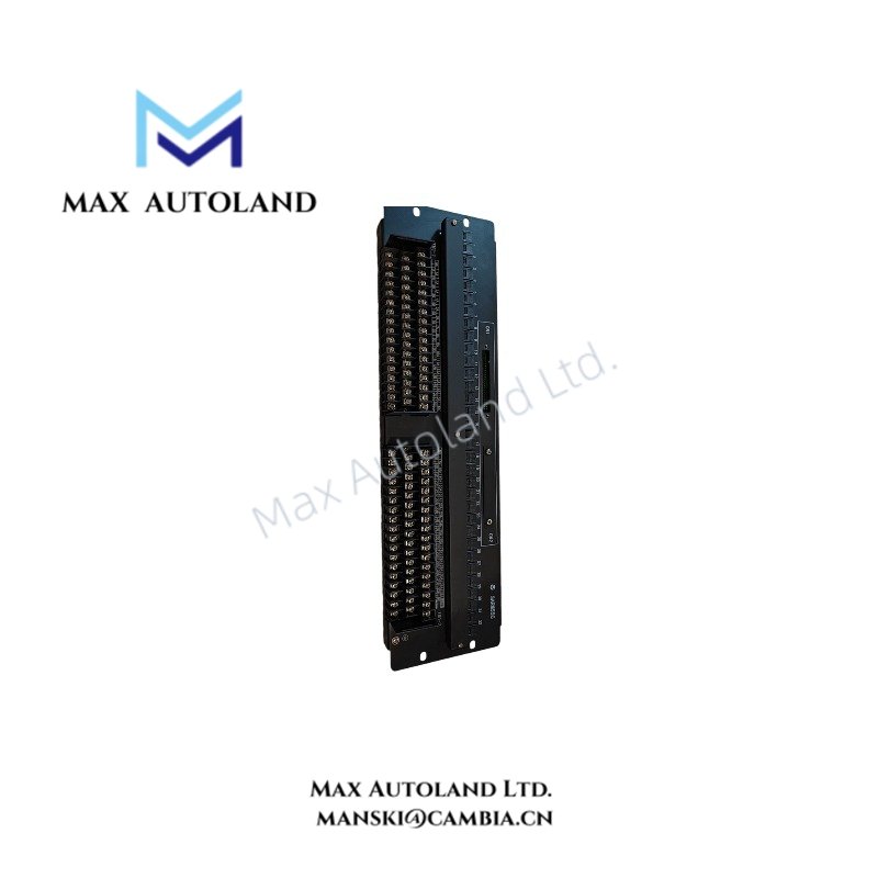
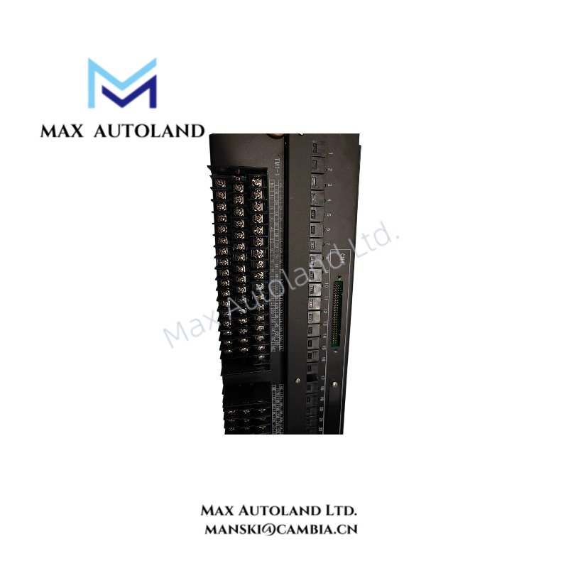
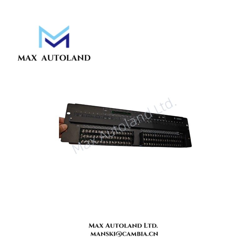

Overview
Hardware Specifications
| Parameter | Specification |
|---|---|
| Model | ARM55C |
| Brand | Yokogawa |
| Product Type | Mechanical Relay Output Board |
| Weight | Approx. 2.2 kg |
| Dimensions | 482.6 mm W x 132.5 mm H |
| Mounting | 19-inch rack, 3U height |
| Operating Temp | 0 to 50 deg C |
| Operating Humidity | 10% to 90% RH, non-condensing |
| Power Consumption | 24 VDC supply; maximum current consumption 0.65 A |
| Number of Channels | 32 relay output channels |
| Contact Type | Dry contacts |
| Contact Configuration | Normally open (NO, a contact) or normally closed (NC, b contact), subject to board configuration |
| Maximum Contact Load | 250 VAC at 2 A per point; 30 VDC at 2 A per point; 125 VDC at 0.1 A per point |
| Minimum Load | 5 VDC, 10 mA |
| Insulation Resistance | At least 10 Mohm at 500 VDC |
| Dielectric Withstand Voltage | Field terminals to case: 2 kVAC for 1 minute |
| Dielectric Withstand Voltage, Power Circuit | 24 V power terminals to case: 500 VAC for 1 minute |
| Dielectric Withstand Voltage, Power to Field | 2 kVAC for 1 minute |
| Signal Cable References | AKB331 for 32-point configuration; AKB337 for 64-point system setups, subject to system compatibility |
| Compatible Digital Output Modules | ADV551 and ADV561, subject to the applicable system configuration |
| Compliance | CE, C-Tick (RCM), and KC markings stated in the supplied data |
Relay Contact Switching and DCS Interface
The ARM55C uses mechanical relay contacts to switch external field circuits. The dry-contact interface allows the control system output to operate a connected load without treating the relay contact as an internally generated field voltage.
Contact selection determines whether the circuit uses a normally open or normally closed contact arrangement. Verify the terminal assignment and board configuration before connecting field wiring.
For process-control installations, distinguish relay contact switching from analog instrumentation functions. The ARM55C is a relay output board; the supplied specifications do not identify it as a 4-20 mA HART interface or a FOUNDATION Fieldbus or Profibus PA communication device.
The maximum load rating varies with the applied voltage. In particular, the stated 125 VDC rating is limited to 0.1 A per point and must not be treated as equivalent to the 2 A ratings at 30 VDC or 250 VAC.
Frequently Asked Questions
Q: What is the output capacity of the ARM55C?
A: The supplied data specifies 32 mechanical relay output channels with dry contacts. Each contact must operate within the stated voltage and current limits.
Q: Can the ARM55C switch both AC and DC loads?
A: The listed ratings include 250 VAC at 2 A per point, 30 VDC at 2 A per point, and 125 VDC at 0.1 A per point. Confirm the load type and electrical characteristics before connection.
Q: Can the ARM55C be used with an ADV561 digital output module?
A: The supplied information lists the ADV561 as a compatible module and references two relay boards for a 64-channel setup. Confirm the exact hardware revision, cable arrangement, and system configuration against the applicable Yokogawa documentation.
Field Installation Guidelines
- Rack mounting: Install the board in the designated 19-inch rack position. Confirm the available 3U mounting space and secure the assembly according to the equipment instructions.
- Power connection: Verify the 24 VDC supply polarity and voltage before energizing the board. Check that the supply can support the stated maximum current consumption of 0.65 A.
- Field wiring: Identify each relay terminal from the applicable terminal diagram. Keep field wiring organized and separated from sensitive analog signal wiring where required by the installation design.
- Contact loading: Check both the load voltage and current against the rating for the applicable AC or DC circuit. Consider inductive load characteristics and provide suitable external suppression where required.
- Grounding and shielding: Follow the system grounding plan. Terminate cable shields according to the applicable installation documentation and avoid creating unintended ground loops.
- Insulation and safety: Isolate power before wiring or servicing. Maintain the required electrical clearances and verify field circuit insulation before commissioning.
- Functional verification: Test the commanded relay states and confirm the expected normally open or normally closed behavior before connecting the board to operating field equipment.
YOKOGAWA Top Products
Customers Also Viewed


Reviews
There are no reviews yet.