
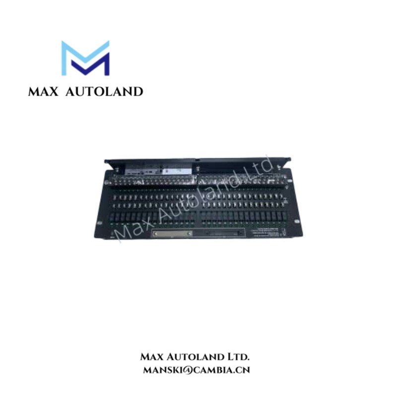
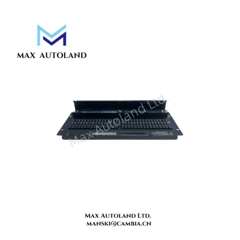
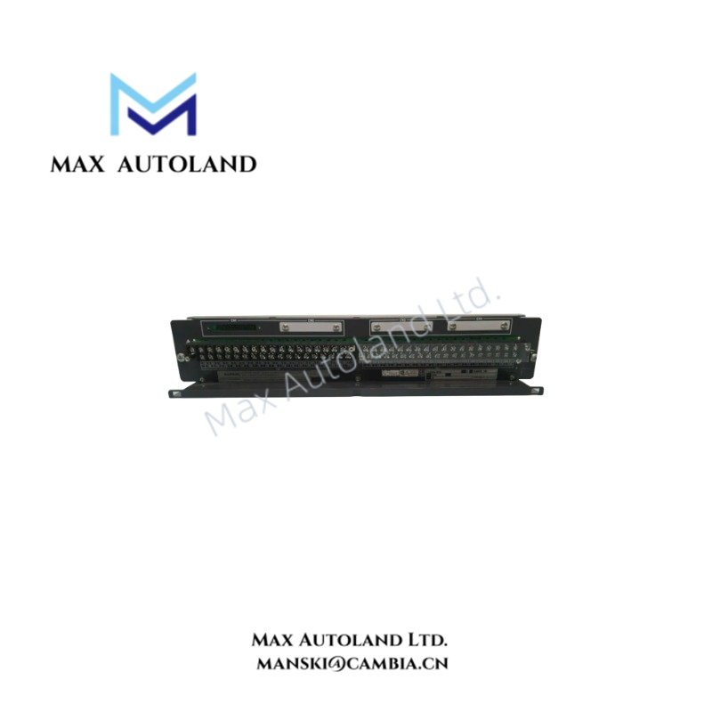
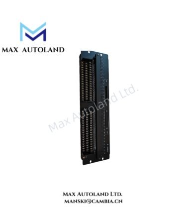
Overview
Hardware Specifications
| Parameter | Specification |
|---|---|
| Model | ARM15A-00/BR3 |
| Brand | Yokogawa |
| Product Type | Mechanical Relay Board |
| System | CENTUM VP FIO |
| Input Type | Dry contact inputs |
| Contact Points | 32 points |
| Field Terminals | M4 screw terminals |
| Compatible Modules | ADV151 (32-point DI with ATD5A terminal block); ADV161 (64-point DI) |
| Signal Cables | AKB331 (32-point); AKB337 (64-point) |
| ON Signal Resistance | 150 ohms or less |
| OFF Signal Resistance | At least 200 kohms |
| Minimum External Contact Rating | 24 VDC, 13 mA |
| Power Supply | 24 VDC |
| Maximum Internal Circuit Current | 0.32 A |
| Field Device Power Supply | Dual-line supply, 24 VDC, maximum 0.3 A per line |
| Insulation Resistance | At least 10 Mohms at 500 VDC |
| Withstanding Voltage | 1.5 kV between field terminals and case; 500 V between 24 V power terminals and case; 1.5 kV between 24 V power terminals and field terminals |
| Operating Temp | 0 to 50 deg C |
| Ambient Humidity | 10 to 90% RH |
| Dimensions | 482.6 mm W x 132.5 mm H, 3U |
| Weight | 2.2 kg |
| Mounting | 19-inch rack mountable |
| Option | /BR3 wall-mount bracket |
Dry Contact Input Signal Interface
The ARM15A receives field contact signals and presents them to the associated digital input module through mechanical relay circuits. The specified ON state requires a contact resistance of 150 ohms or less, while the OFF state requires at least 200 kohms. These values define the contact conditions for signal recognition.
The board supports single or dual-redundant digital I/O arrangements. Field wiring must match the assigned terminal points and the applicable Yokogawa connection diagram. The board also requires an external 24 VDC supply for its internal circuitry; this supply is separate from the field device power supply.
Frequently Asked Questions
Q: Which digital input modules are listed for use with the ARM15A?
A: The supplied specifications list the ADV151 with an ATD5A terminal block for 32-point digital input and the ADV161 for 64-point digital input. Confirm the applicable cable and system configuration before installation.
Q: What contact resistance defines the ON and OFF states?
A: The specified ON signal resistance is 150 ohms or less. The specified OFF signal resistance is at least 200 kohms.
Q: What power supplies does the ARM15A require?
A: The internal circuit requires an external 24 VDC supply with a maximum current of 0.32 A. The field device power supply uses a dual-line arrangement, with 24 VDC and a maximum of 0.3 A per line.
Field Installation Guidelines
- Verify the board model, suffix codes, mounting arrangement, and compatibility with the target FIO subsystem before installation.
- Secure the board in the designated rack or use the specified /BR3 wall-mount bracket where applicable.
- Connect field contact wiring to the designated M4 screw terminals according to the system wiring diagram.
- Separate field signal wiring from power wiring where practical to reduce electrical interference. Apply the cabinet grounding and shielding practices specified by the system design.
- Verify the polarity and voltage of the external 24 VDC supply before energizing the board. Check the internal circuit supply and field device supply independently.
- Confirm the field contact states against the specified ON and OFF resistance limits before connecting the system to live control operations.
- Check terminal tightness, cable identification, and wiring continuity. Follow the applicable Yokogawa maintenance and installation procedures.
YOKOGAWA Top Products
Customers Also Viewed




Reviews
There are no reviews yet.