
Overview
Suffix Breakdown & Model Matrix
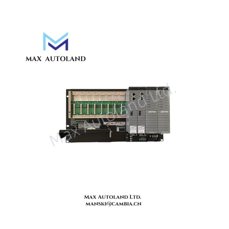
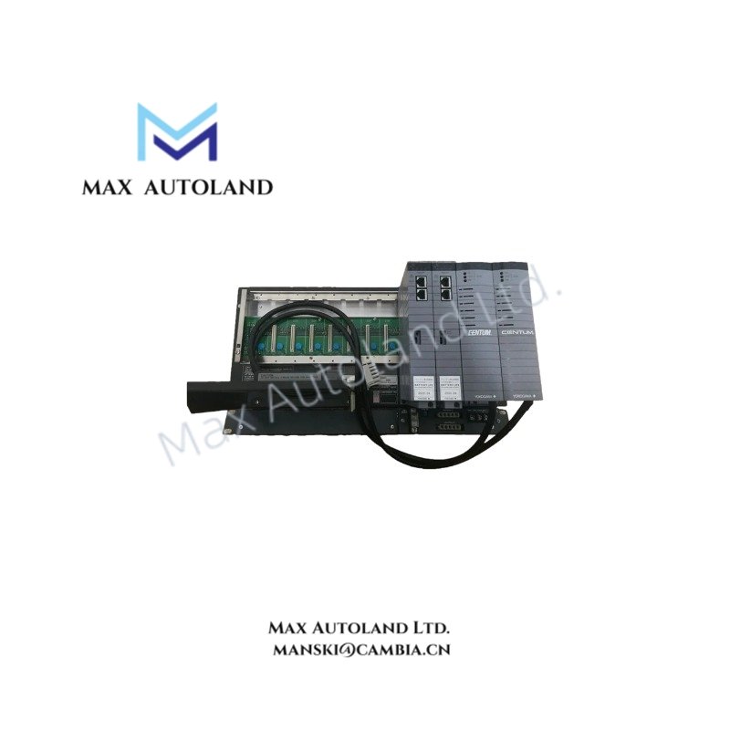
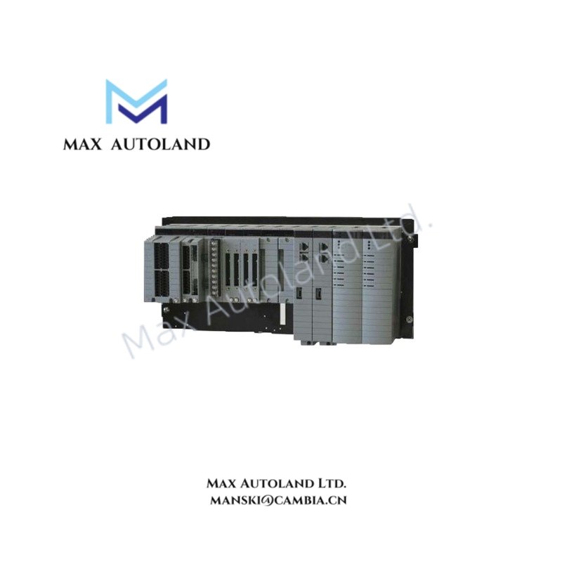
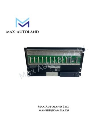
The supplied documentation defines the ordering structure for the AFV10D series.
| Item | Description |
|---|---|
| Base Model | AFV10D |
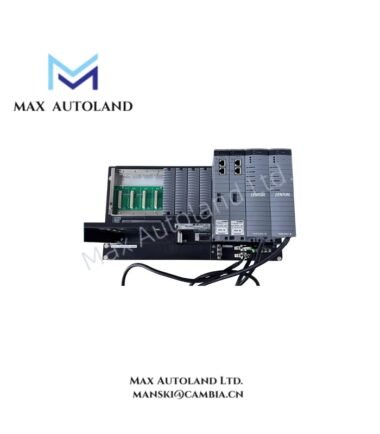
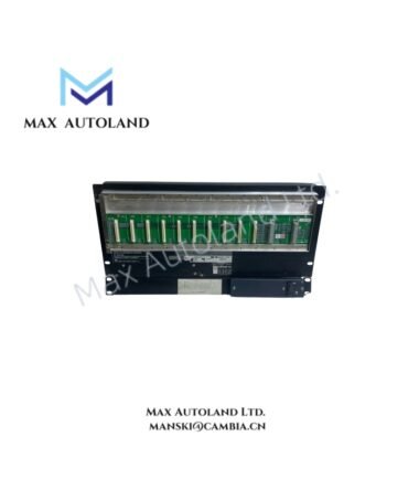
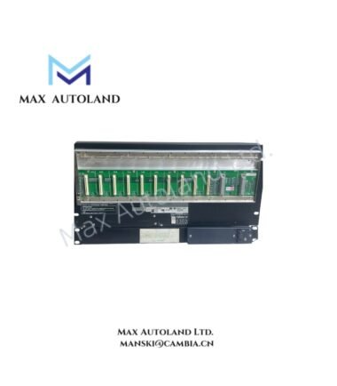
| Product | Duplexed Field Control Unit for Vnet/IP and FIO |
| Type | Standard (-S) |
| Redundancy | Dual-redundant Vnet/IP and dual-redundant power supply |
| Power Supply Options | 100 – 120 VAC / 220 – 240 VAC / 24 VDC |
| Protection Options | Basic, ISA Standard G3, Explosion Protection variants |
| Optional Software | LFS1500 Control Function, LFS1550 Application Capacity Expansion |
| Optional License | /NDEL Node Unit Expansion License |
| Optional Documentation | /ATDOC Explosion Protection Manual |
Hardware Specifications
| Parameter | Specification |
|---|---|
| Model | AFV10D-S41451 |
| Brand | Yokogawa |
| Origin | Japan |
| Product Type | Duplexed Field Control Unit |
| Processor | VR5432, 133 MHz |
| Main Memory | 32 MB |
| Memory Backup | Battery-backed RAM, maximum 72 hours |
| Battery Recharge Time | Minimum 48 hours |
| Communication Network | Dual-redundant Vnet/IP |
| FCU Status Output | 2 terminals (NC, C), contacts open during FCU failure |
| Contact Rating | 30 VDC, maximum 0.3 A |
| Maximum Node Units | 14 total (maximum 9 ESB Bus Node Units) |
| ESB Bus Interface | EC401 Bus Coupler Module |
| ER Bus Interface | EB401 Interface Master Module |
| Processor Modules | Dual CP451 |
| Power Supply Modules | Dual PW481, PW482, or PW484 |
| Maximum I/O Modules | 8 |
| Mounting | 19-inch rack, 8 × M5 screws |
| Network Connection | CAT5e or higher UTP cable to Layer 2 switch |
| Weight | Approx. 8 kg |
| Operating Temp | Refer to Vnet/IP System Overview (GS33K01A10-50E) |
| Power Supply | 100 – 120 VAC, 220 – 240 VAC, or 24 VDC (suffix dependent) |
| Power Consumption | 200 VA (100 – 120 VAC), 230 VA (220 – 240 VAC), 5.5 A (24 VDC) |
| Safety Standards | CSA, CE (power supply dependent) |
| EMC Compliance | CE, C-Tick, KC (configuration dependent) |
Channel Isolation and Process Control Integration
The AFV10D operates within the Yokogawa Vnet/IP architecture using dual communication interfaces to maintain processor synchronization between redundant control paths. Connection to distributed FIO hardware is accomplished through EC401 ESB Bus Coupler Modules or EB401 ER Bus Interface Master Modules, depending on the selected I/O architecture.
The control station supports expansion through licensed Node Unit connections. A maximum of 14 node units can be connected to one FCU, subject to the ESB Bus limitation of nine node units. Installation of the LFS1550 Application Capacity Expansion Package extends the supported node count from three to fourteen when used with LFS1500.
Frequently Asked Questions
Q: Can processor redundancy be configured with only one communication interface module installed?
A: No. In a dual-redundant processor configuration, the EC401 modules are installed in both Slot 7 and Slot 8. A single EC401 installation applies only to single ESB Bus configurations.
Q: Is an expansion license required when additional node units are connected?
A: Yes. Each additional Node Unit connected to the FCU requires the /NDEL Node Unit Expansion License.
Q: Does the controller support multiple power supply configurations?
A: Yes. The hardware is available for 100 – 120 VAC, 220 – 240 VAC, or 24 VDC operation. The applicable power supply is determined by the ordering suffix.
Field Installation Guidelines
- Install the controller in a standard 19-inch equipment rack using the specified M5 mounting hardware.
- Connect the protective earth conductor to the designated M4 grounding terminal before applying operating power.
- Route network cables separately from AC power wiring to reduce conducted electrical noise.
- Use CAT5e or higher UTP cable for Vnet/IP network connections through a Layer 2 Ethernet switch.
- Install EC401 modules only in the designated slots for ESB Bus communication.
- For ER Bus systems, install the EB401 Interface Master Module in an odd-numbered slot and leave the adjacent slot unoccupied as specified by the hardware configuration.
- Verify battery condition periodically to maintain RAM retention during power interruption.
- Confirm the selected power supply option matches the hardware suffix before energizing the unit.
Emerson Top Products
| Emerson DeltaV | Epro | Ovation/Westinghouse |
| KJ1501X1-BC3 | 9100-00049-03 | 1C31122G01 |
| KJ3202X1-BA1 | A6110 | 1C31125G03 |
| KJ3222X1-BA1 | A6120 | 1C31232G01 |
| KJ3243X1-BA1 | A6125 | 1C31147G01 |
| KJ3002X1-BG1 | A6140 | 1B30035H01 |
| KJ3002X1-BB1 | A6210 | 1B30023H02 |
| KJ3001X1-BB1 | A6220 | 1B30023H01 |
| KJ3002X1-BC1 | A6312 | 1C31132G01 |
| KJ3002X1-BF1 | A6312/06 | 1C31129G03 |
| KJ3001X1-BJ1 | A6312/08 | 5X00119G01 |
Customers Also Viewed
| Bently Nevada | ABB | Yokogawa | Woodward | Schneider |
| 133835-02 | SPDSM04 | CP451-10 | 5463-785 | 140CPU65150 |
| 135321-01 | SPIEET800 | CP461 | 5437-672 | BMEXBP0400 |
| 135322-01 | SPINIET800 | CP461-50 | 9907-175 | 140CPU67160 |
| 136751-01 | SPNLK01 | CP451-11 | 5466-355 | 170FNT11001 |
| 136751-02 | SPSED01 | CP701 S1 | 5466-257 | 170ADO34000 |
| 184139-10 | SPSEM11 | CP345 S1 | 5466-1049 | 170ADM35010 |
| 82362-01 | SPSET01 | SCP461-11 S1 | 5501-381 | 170ADI34000 |
| 84134-01 | SPTKM01 | CP451-10 S2 | 8200-177 | 140ARI03010 |
| 87900-02 | SPTPS02 | CP401-10 | 8200-205 | BMXCPS4002 |
| 89998-01 | SPTPS13 | NFCP100-S00 | 9907-029 | 140CRP93200 |

Reviews
There are no reviews yet.