
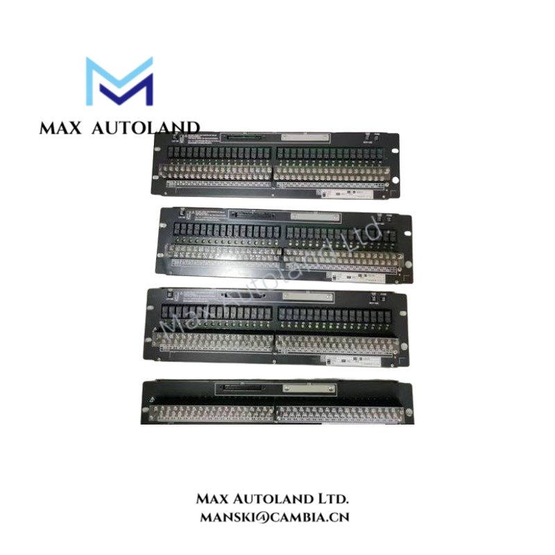
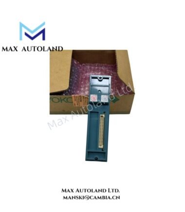
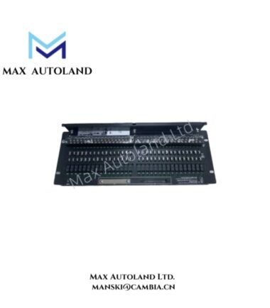
Overview
Hardware Specifications
| Parameter | Specification |
|---|---|
| Model | AED5D |
| Alternative Inventory Reference | SAED5D |
| Brand | Yokogawa |
| Product Type | Digital Terminal Board |
| Weight | Approximately 1.8 kg |
| Terminal Points | 32 |
| Terminal Connection | M4 screw terminals |
| Insulation Resistance | 100 MOhm or greater at 500 VDC |
| Withstanding Voltage | 500 VAC for 1 minute |
| System Compatibility | CENTUM VP / CENTUM CS 3000 FIO compatibility requires confirmation against the applicable hardware manual |
| Signal Connection | Dedicated signal cable; verify the compatible cable model |
DCS Field Wiring and Electrical Insulation
The terminal board provides a physical termination point for field wiring. Its 32 M4 screw terminals support conductor connection and circuit identification during installation and maintenance.
For Yokogawa DCS installations, verify the associated I/O module type, signal allocation, terminal assignment, and cable pinout before wiring. Do not assume that the board supports a particular 4-20 mA HART loop, FOUNDATION Fieldbus, or Profibus PA interface without confirmation from the model-specific documentation.
The stated insulation resistance and withstand voltage are electrical insulation specifications. They do not establish channel-to-channel isolation, surge immunity, or hazardous-area certification.
Frequently Asked Questions
Q: How many field connections does the AED5D provide?
A: The supplied specifications identify 32 terminal points with M4 screw connections. Confirm the terminal numbering and signal allocation using the applicable connection diagram.
Q: Can the AED5D be used in a redundant DCS configuration?
A: The supplied description states that single and dual-redundant configurations are supported. Confirm the supported I/O module combination, cable arrangement, and redundancy topology in the relevant Yokogawa hardware manual.
Q: What electrical insulation values are specified for this terminal board?
A: The supplied data specifies an insulation resistance of at least 100 MOhm at 500 VDC and a withstand voltage of 500 VAC for 1 minute. Apply the manufacturer’s prescribed test procedure before performing any insulation test on installed equipment.
Field Installation Guidelines
- Verify hardware identification. Check the board nameplate and complete ordering code before installation. Do not treat AED5D and SAED5D as interchangeable ordering codes without confirmation.
- Confirm terminal assignments. Match each field conductor to the manufacturer’s terminal diagram and the configured I/O channel.
- Check cable compatibility. Use the specified signal cable and verify connector orientation and pin assignments before energizing the system.
- Separate signal wiring. Route low-level instrumentation signals separately from power conductors and other sources of electrical interference, following the applicable installation requirements.
- Apply grounding and shielding correctly. Terminate cable shields according to the Yokogawa system grounding design. Avoid creating unintended ground loops.
- Inspect screw terminals. Check conductor preparation, terminal engagement, and tightening torque against the manufacturer’s instructions.
- Verify the completed installation. Perform continuity checks and appropriate loop checks before placing the associated control circuits into service. Isolate the equipment and follow approved electrical safety procedures before making wiring changes
YOKOGAWA Top Products
Customers Also Viewed


Reviews
There are no reviews yet.