

Overview
Hardware Specifications
| Parameter | Specification |
|---|---|
| Model | 3300/20 |
| Brand | Bently Nevada |
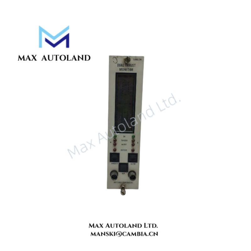
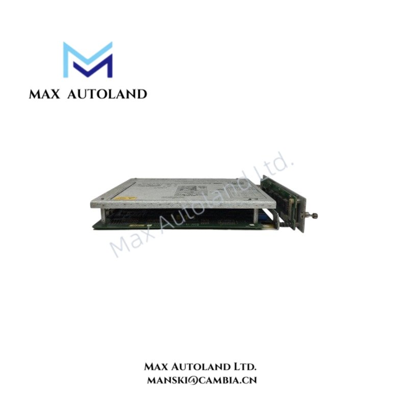
| Product Type | Dual Thrust Position Monitor |
| Measurement | Shaft axial position |
| Input Channels | One or two proximity probe inputs |
| Input Impedance | 10 kOhm |
| Input Sensitivity | 200 mV/mil (8 V/mm) or 100 mV/mil (4 V/mm) |
| Power Consumption | 1.5 W nominal |
| Signal Conditioning Accuracy | Typically +/-0.33% of full scale; +/-1% maximum |
| Accuracy Reference Temperature | 25 deg C |
| Recorder Output Options | +4 to +20 mA, 0 to -10 VDC, or +1 to +5 VDC |
| Recorder Output Accuracy, +4 to +20 mA | +/-0.7% of signal, +/-0.09 mA offset |
| Recorder Output Accuracy, +1 to +5 VDC | +/-1.1% of signal, +/-10 mV offset |
| Recorder Output Accuracy, 0 to -10 VDC | +/-1.1% of signal, +/-15 mV offset |
| Voltage Output Impedance | 100 Ohm |
| Minimum Voltage Output Load | 10 kOhm |
| Current Output Compliance | 0 to +12 VDC across the load |
| Current Output Load Resistance | 0 to 600 Ohm for the +4 to +20 mA option |
| Buffered Output Impedance | 100 Ohm |
| Transducer Supply Voltage | -24 VDC or -18 VDC |
Measurement and Channel Operation
The monitor tracks axial shaft movement against the available thrust bearing clearance. Where the probe installation allows direct observation of the thrust collar, the measurement represents the collar’s axial position relative to the bearing clearance. This arrangement helps maintenance personnel assess axial movement and identify conditions that may indicate thrust bearing deterioration.
The monitor accepts one or two proximity probe signals. Each configured channel provides an independent recorder output, allowing external instrumentation to receive a signal proportional to the programmed full-scale range. The selected input sensitivity must match the applicable probe and measurement configuration.
Signal Outputs and Transducer Supply
The recorder output can use one of three formats: +4 to +20 mA, 0 to -10 VDC, or +1 to +5 VDC. The monitor scales the selected output to its programmed full-scale range. Output accuracy includes the specified signal-conditioning accuracy plus the additional error and offset listed for each output format.
Buffered transducer signals are available through front-panel coaxial connectors and rear-panel terminals. These connections support access to the probe signals for external monitoring or testing. The monitor also provides a programmable -24 VDC or -18 VDC transducer supply, with current limiting on the individual monitor circuit board.
Compatibility note: The source documentation advises contacting a sales professional when a monitoring system combines 3000 Series transducers with 3300 Series and/or 7200 Series transducers. Confirm the complete probe and monitor configuration before combining these transducer families.
Frequently Asked Questions
Q: How many proximity probes can the 3300/20 accept?
A: The monitor accepts one or two proximity probe signal inputs. Confirm the intended channel configuration and probe arrangement when selecting a replacement.
Q: Which recorder output formats does the 3300/20 support?
A: It supports +4 to +20 mA, 0 to -10 VDC, and +1 to +5 VDC. The output format is user-programmable, and each channel has an independent recorder output.
Q: Can the 3300/20 supply power to its proximity probes?
A: Yes. The monitor provides a user-programmable transducer supply of -24 VDC or -18 VDC. Verify the required supply voltage and transducer compatibility before installation.


Reviews
There are no reviews yet.