

Overview
Technical Specifications
| Parameter | Specification |
|---|---|
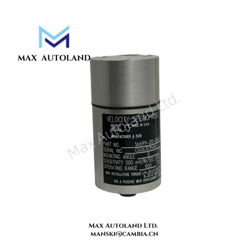
| Model | 16699-10-02-02 |
| Brand | Bently Nevada |
| Product Type | Velocity Seismoprobe |
| Sensor Type | Moving-coil velocity transducer |
| Frequency Response | 10 Hz to 1,000 Hz |
| Sensitivity | 20 mV/mm/s nominal |
| Output Signal | AC voltage proportional to vibration velocity |
| Operating Temperature | -35 deg C to +100 deg C |
| Weight | Approximately 140 g |
| Mounting Base | Circular base |
| Mounting Stud | 1/4-28 UNF |
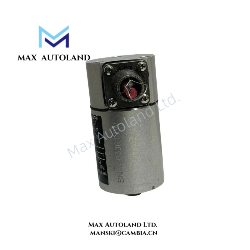
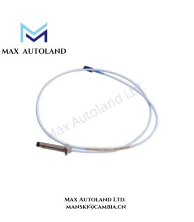
| Connector | Top-mounted, two-pin MIL-style connector |
Operating Principle and Signal Output
The moving coil responds to vibration relative to the sensor’s internal magnetic assembly. This motion generates an AC voltage related to vibration velocity, allowing connected monitoring equipment to evaluate casing or structural vibration. The sensor measures absolute vibration rather than shaft-relative displacement, so its measurement function differs from that of an eddy-current proximity probe.
Configuration Identification
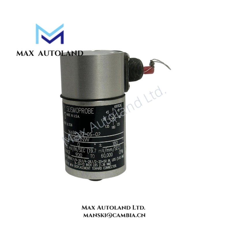
The supplied suffix matrix describes three configuration fields: mounting angle and minimum operating frequency, mounting base, and connector mounting. However, the listed sensitivity of 100 mV/mm/s conflicts with the overview’s nominal 20 mV/mm/s value. Confirm the applicable configuration documentation before using these codes to specify calibration or operating limits.
For maintenance and replacement purposes, verify the complete part number and physical connector and mounting arrangement against the installed sensor. Do not select a replacement based on the model prefix alone.
Frequently Asked Questions
Q: Does the 16699-10-02-02 require an external power supply?
A: A passive moving-coil velocity transducer generates its own AC measurement signal and does not require external excitation for the sensing principle. The receiving monitor must support the transducer’s electrical characteristics.
Q: What does the output signal represent?
A: The output voltage is proportional to the velocity of the monitored casing or structure within the applicable frequency response and calibration conditions. It does not directly represent shaft displacement.
Q: Which mounting and connector details should be checked before ordering?
A: Verify the 1/4-28 UNF mounting stud and top-mounted two-pin connector against the actual unit. Also confirm the required mounting orientation and minimum operating frequency for the intended measurement.



Reviews
There are no reviews yet.