Overview
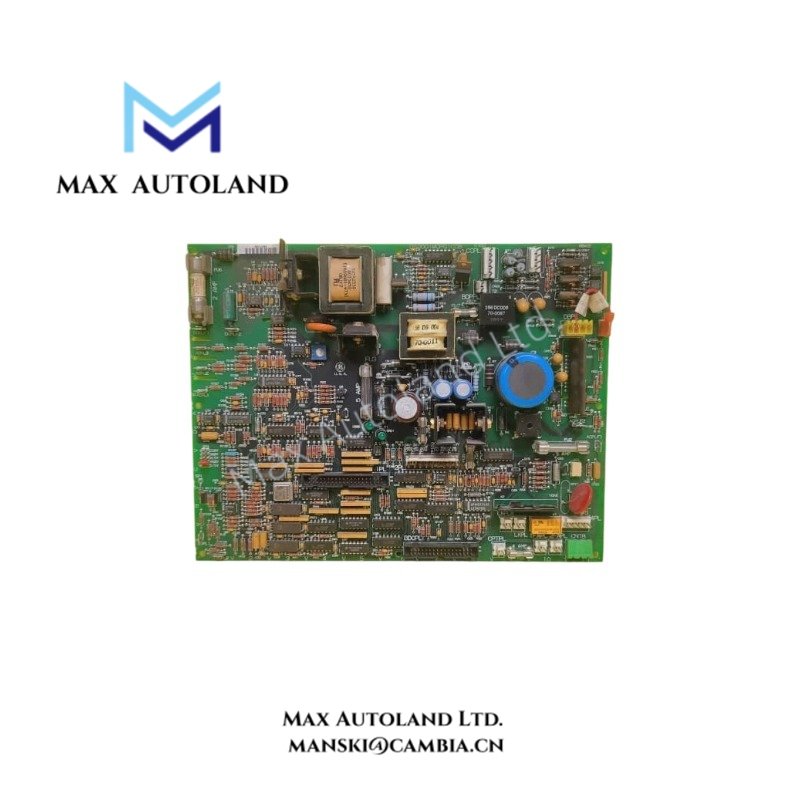
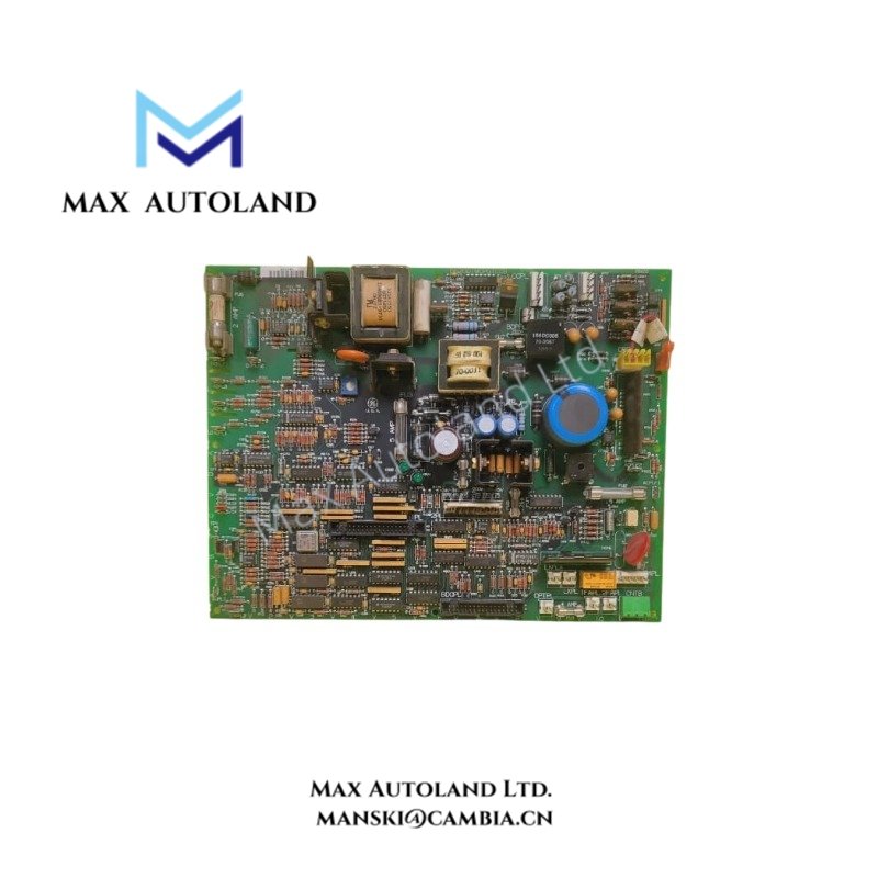
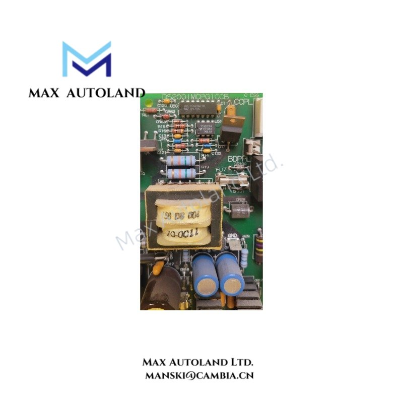
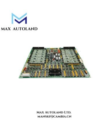
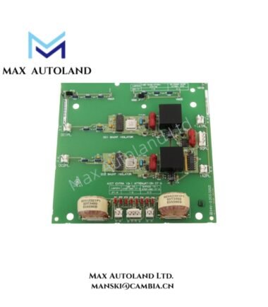
The GE DS200IMCPG1CCB, also identified by the base model DS200IMCPG1, is an I/O power supply interface module associated with GE industrial control hardware. Its exact electrical interface and compatibility with the Mark V control system require confirmation against the applicable GE documentation. The supplied specifications contain conflicting power supply ratings, so unverified values are excluded from confirmed operating limits.
Hardware Specifications
| Parameter | Specification |
|---|---|
| Model | DS200IMCPG1CCB |
| Brand | General Electric (GE) |
| Series | Drive Control; Mark V association requires verification |
| Product Type | I/O Power Supply Interface Module |
| Origin | United States |
| Weight | 0.3-1.5 kg |
| Dimensions | Height: 15.9 cm; second dimension: 17.8 cm |
| Operating Temp | -10 to +60 deg C |
| Power Consumption | Not verified |
| Input Voltage | 100-240 VAC |
| Output Voltage | 5 VDC, 12 VDC, 24 VDC |
| Output Current | 1-10 A |
| Power Rating | 10-250 W |
| Additional Voltage Entry | 28 VDC |
| Output Frequency Range | 0-500 kHz |
| Mounting | DIN-rail mounting listed in supplied data; mechanical compatibility unverified |
| Technology | Surface mount listed in supplied data |
GE Drive Control and Backplane Compatibility
GE control hardware uses board-specific electrical interfaces and connector assignments. Therefore, the DS200IMCPG1CCB must be matched to the intended equipment using its complete part number and the applicable hardware documentation.
Before connecting this module, verify the supply input range, output rail assignments, connector pinout, grounding arrangement, and permitted load current. The supplied data does not establish whether the stated AC input, 28 VDC entry, and multiple DC outputs refer to the same assembly or to different power circuits.
Do not assume that the listed DIN-rail mounting method, output frequency range, or protection functions apply to this specific board without manufacturer documentation.
Frequently Asked Questions (FAQ)
Q: What power supply input does the DS200IMCPG1CCB support?
A: The supplied information lists 100-240 VAC and separately mentions 28 VDC. The applicable input rating and the relationship between these entries require verification before energizing the module.
Q: What output voltages does the module provide?
A: The supplied data lists 5 VDC, 12 VDC, and 24 VDC. The available rails, current limits, and connector assignments have not been independently verified.
Q: Is the DS200IMCPG1CCB compatible with every GE Mark V or drive control rack?
A: Compatibility cannot be established from the part number alone. Check the equipment bill of materials, board revision, connector arrangement, and manufacturer-approved replacement documentation before installation.
Field Installation Guidelines
- Isolate the equipment power supply and follow the site’s lockout/tagout procedure before handling the module.
- Confirm the full part number, board revision, and intended installation location against the equipment documentation.
- Verify the input voltage, output rails, connector pinout, and load requirements before making electrical connections.
- Inspect connectors and the PCB for damaged contacts, contamination, or visible component damage.
- Route power wiring separately from low-level signal wiring where practical. Follow the equipment manufacturer’s grounding and shielding requirements.
- Do not apply power until the conflicting electrical ratings have been resolved using an authoritative datasheet or system schematic.
- After installation, verify supply voltages and system status using approved commissioning procedures.