

Overview
Hardware Specifications
| Parameter | Specification |
|---|---|
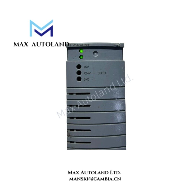
| Model | PW484-51 |
| Base Model | PW484 |
| Brand | Yokogawa |
| Product Type | 24 VDC Input Power Supply Module |
| Input Voltage | 24 VDC +/- 10% |
| Current Rating | 5.5 A |
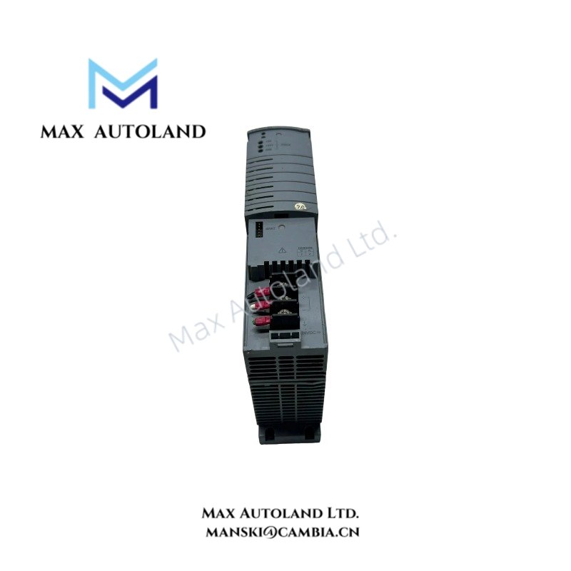
| Connection Interface | Exclusive connector |
| Weight | Approx. 1 kg |
| Operating Temp | -20 to 70 deg C for the stated ISA Standard G3 option |
| Explosion Protection | Depends on the applicable suffix code |
| Corrosion Resistance | ISA Standard G3 option, subject to model configuration |
DCS Power Supply and Environmental Configuration
The PW484 belongs to Yokogawa’s 24 VDC input power supply module range. Its electrical interface uses a dedicated connector rather than a general-purpose field wiring terminal.
The supplied suffix information identifies the following configuration options:
- -S: Standard type without explosion protection.
- -E: Standard type with explosion protection.
- 0: Basic type.
- 1: ISA Standard G3 option with a stated temperature range of -20 to 70 deg C.
The exact ordering-code interpretation for PW484-51 should be verified against the applicable Yokogawa model and suffix-code documentation before installation. The available information does not independently establish the module’s output rating, power consumption, or compatibility with specific FCU and FIO configurations.
Frequently Asked Questions
Q: What input voltage does the PW484-51 require?
A: The supplied specification lists 24 VDC +/- 10%. Verify polarity and connection assignments against the applicable equipment documentation before energizing the module.
Q: What connector does the PW484 use?
A: It uses an exclusive connector. Confirm the matching connector type, module slot, and pin assignments from the system hardware manual.
Q: Can two PW484 modules operate in a redundant configuration?
A: The supplied data does not confirm the redundancy configuration or switching behavior for the PW484-51. Check the applicable Yokogawa system manual for supported module combinations, slot assignments, and replacement procedures.
Field Installation Guidelines
- Verify the complete model code and suffix configuration against the equipment bill of materials.
- Isolate the relevant power source and follow the system’s electrical safety procedures before inserting or removing the module.
- Inspect the exclusive connector for damage, contamination, or bent contacts before installation.
- Confirm input voltage, polarity, connector pinout, and the equipment’s current requirements using the manufacturer’s documentation.
- Keep power wiring separate from noise-sensitive analog signal and communication wiring where the cabinet design permits.
- Apply cabinet grounding and bonding practices specified by the system manufacturer.
- Do not assume hot-swap capability, redundant operation, or explosion-protection approval without confirmation for the exact configuration.
YOKOGAWA Top Products
Customers Also Viewed


Reviews
There are no reviews yet.