


Overview
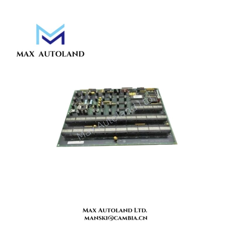
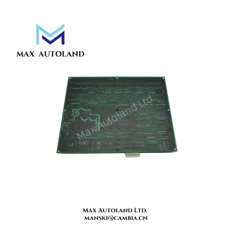
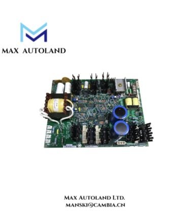
The GE DS215UCVBG1AJ is a Module Genius Controller designed for the Mark V Speedtronic turbine control system. It features an Ethernet connection, configuration switches, status LEDs, and a connector for hard disk drive attachment. Furthermore, its local interface supports keyboard and monitor connections, allowing operators to access diagnostic tools and review controller warnings and errors.
Technical Specifications
| Parameter | Specification |
|---|---|
| Model | DS215UCVBG1AJ |
| Brand | GE (General Electric) |
| Series | Mark V Speedtronic |
| Functional Acronym | UCVB |
| Product Type | Module Genius Controller |
| Assembly Type | DS215 Special Assembly |
| Mark V Series Grouping | Group 1 |
| Functional Revision | A |
| Secondary Functional Revision | J |
| Revision Quantity | 2 |
| PCB Coating | Normal Coating |
| Ethernet Interface | 1 Ethernet connector |
| Configuration Switches | 2 switch blocks |
| LAN Node Address Range | 0-255 |
| Configuration Switch Count | 8 switches |
| Diagnostic Indicators | Status LEDs and indicator LEDs |
| Additional Connections | Hard disk drive connector; keyboard and monitor connections |
Controller Interfaces and Configuration
The DS215UCVBG1AJ provides an Ethernet connection for network communication. Its two configuration switch blocks allow operators to set the controller’s local dLAN node number. Eight switches represent the node address in hexadecimal, covering values from 0 to 255.
In addition, the controller provides a connector for hard disk drive attachment. Operators can also connect a keyboard and monitor to access the controller’s user interface and troubleshooting tools.
LED Status and Diagnostics
The front panel includes status LEDs and indicator LEDs that help operators check controller activity and identify faults.
- Status LEDs: Display controller error codes in hexadecimal format, allowing operators to identify reported errors without opening the troubleshooting interface.
- ENET LED: Flashes when Ethernet network activity is present.
- OK LED: Lights when the controller receives power, operates normally, and has no fatal errors.
Furthermore, operators can use the troubleshooting interface to review logs containing previously recorded warnings and errors. These diagnostic functions help distinguish network activity, normal processing status, and reported controller faults.
Installation and Removal
The controller connects to the rack through connectors on its rear side. When installing the board, align the rear connectors with the corresponding rack connections and slide the controller into position.
To remove the controller:
- Open the top and bottom extractor levers.
- Grasp the controller and pull it out of the rack.
Frequently Asked Questions
Q: How do operators configure the DS215UCVBG1AJ dLAN node number?
A: Operators use the eight configuration switches on the controller to set the local dLAN node address. The available address range is 0-255, represented in hexadecimal.
Q: What do the ENET and OK LEDs indicate?
A: The ENET LED flashes when Ethernet network activity occurs. Meanwhile, the OK LED indicates that the controller receives power, processes normally, and has no fatal errors.
Q: Can the DS215UCVBG1AJ display controller error logs?
A: Yes. Operators can connect a keyboard and monitor to access the controller’s user interface and troubleshooting tools. They can then review recorded warnings and errors.


