



Overview
Hardware Specifications
| Parameter | Specification |
|---|---|
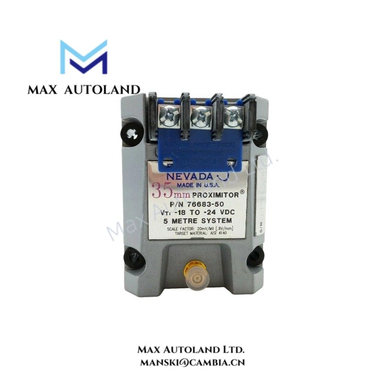
| Model | 76683-50 |
| Brand | Bently Nevada |
| Product Family | 7200 Proximity Transducer Systems |
| Component Type | Machinery Monitoring Component |
| Exact Part Number | 76683-50 |
| Channel Capacity | 2 channels |
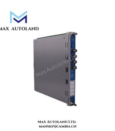
| Rack Space | One full-height slot |
| Backplane Supply | 3500/3300 rack power |
| Input Type | Condition-monitoring transducer |
| Alarm Outputs | Alert and Danger levels |
| Status LEDs | OK, TX/RX and Bypass |
| Buffered Output | Front-panel transducer signal |
| Configuration | Rack configuration software |
| Relay Logic | Programmable alarm voting |
Eddy-Current Probe Signal Validation
For machinery monitoring applications using eddy-current proximity probes, installation should verify the probe signal and mechanical gap against the requirements of the connected monitoring circuit. A typical eddy-current probe system uses a DC gap voltage to establish the probe operating point. The commonly referenced target for many Bently Nevada probe systems is approximately -10 VDC, but the applicable value must be confirmed against the specific probe and monitor configuration.
The 76683-50 input is specified as a condition-monitoring transducer interface. Therefore, probe scaling, gap-voltage validation, and signal conditioning should follow the documentation for the complete installed transducer circuit rather than being inferred solely from the part number.
Frequently Asked Questions
Q: How many monitoring channels does the 76683-50 provide?
A: The supplied specification identifies a 2-channel capacity.
Q: What rack space does the 76683-50 require?
A: The supplied specification identifies one full-height rack slot.
Q: Does the 76683-50 provide alarm status indication?
A: Yes. The supplied configuration specifies Alert and Danger alarm levels, with OK, TX/RX, and Bypass status LEDs.
Field Installation Guidelines
Install the component in the specified full-height rack position and verify mechanical engagement before applying power. Confirm that the installed rack provides the stated 3500/3300 rack power interface.
Connect the condition-monitoring transducer wiring according to the applicable system wiring documentation. Keep transducer signal wiring separated from high-current switching conductors and other sources of electrical interference.
For eddy-current probe circuits, verify probe polarity, signal continuity, and the required operating gap before commissioning. Where shielded cable is used, terminate the shield according to the installed system grounding design and avoid creating unintended ground loops.
Verify the front-panel buffered transducer output before connecting external monitoring equipment. Check the OK, TX/RX, and Bypass indicators during commissioning, then verify the configured Alert and Danger alarm logic under controlled test conditions.






Reviews
There are no reviews yet.