
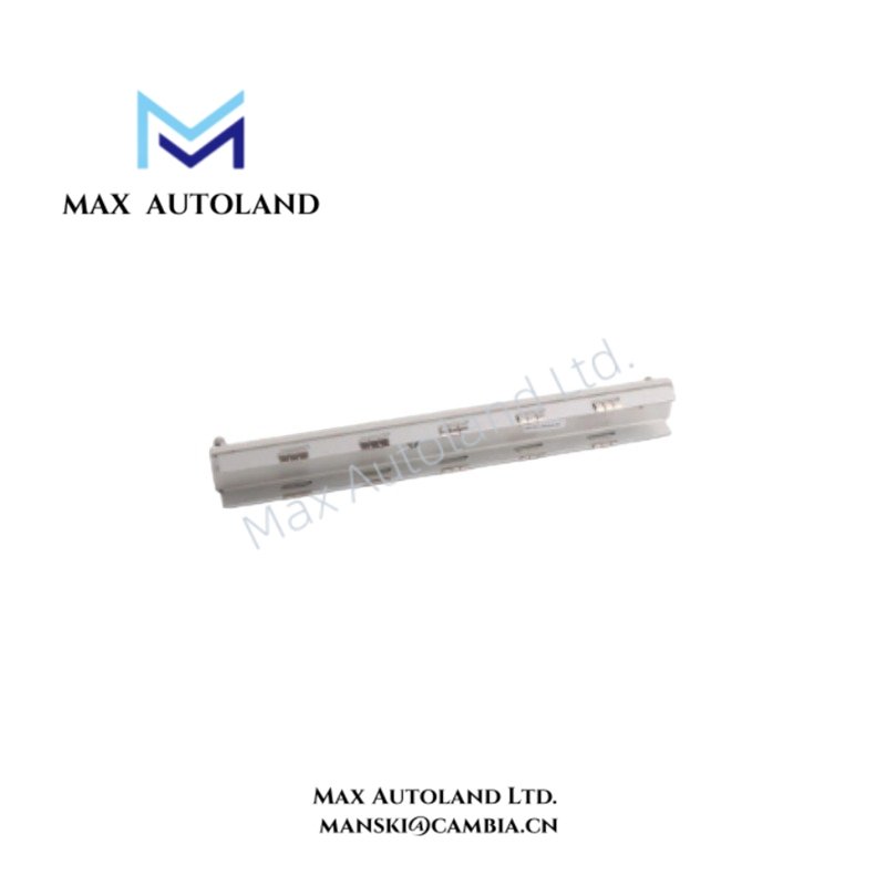




Overview
Suffix Breakdown & Model Matrix
The supplied information identifies 128228-01 as a fixed part number. No manufacturer-defined suffix or variant matrix is provided, so no suffix interpretation is assigned.
Hardware Specifications
| Parameter | Specification |
|---|---|
| Model | 128228-01 |
| Brand | Bently Nevada |
| Manufacturer | Bently Nevada, Baker Hughes |
| Product Type | Interface Module / Machinery Protection Component |
| Primary Application | Vibration analysis, machinery health monitoring, machinery protection |
| Origin | USA |
| Operating Temp | -40 deg C to +85 deg C |
| Input Voltage | 110 to 240 VAC |
| Output Signals | Relay contacts, standard analog outputs |
| Communication Protocol | Modbus RTU |
| Signal Type | Vibration monitoring signals; exact input characteristics not specified |
Rotor Dynamics and Signal Interface
The 128228-01 is specified for machinery protection and vibration monitoring. Its documented interfaces include relay contacts, analog outputs, and Modbus RTU communication. These interfaces can carry monitoring or protection status to associated control or supervisory equipment.
The supplied information does not specify eddy-current probe scaling, input channel count, gap-voltage range, analog output range, relay contact ratings, Modbus electrical interface, or signal conditioning parameters. These values should be confirmed against the applicable Bently Nevada documentation before system integration.
Frequently Asked Questions
Q: What supply voltage is specified for the 128228-01?
A: The supplied specification identifies an input voltage range of 110 to 240 VAC.
Q: Which output interfaces are specified?
A: The supplied data specifies relay contacts and standard analog outputs. Exact output ranges and contact ratings are not provided.
Q: Does the 128228-01 support Modbus RTU?
A: Yes. The supplied technical data identifies Modbus RTU as the communication protocol. The physical electrical interface and communication parameters are not specified.
Field Installation Guidelines
Verify the 110 to 240 VAC supply requirements and protective isolation before energizing the module. Confirm terminal identification from the applicable hardware documentation.
Separate vibration-monitoring signal wiring from high-voltage and high-current conductors where practical. Follow the equipment manufacturer’s requirements for cable shielding and shield termination.
Connect relay and analog outputs only to equipment with compatible electrical ratings. Verify the receiving device input range before applying an analog signal.
For Modbus RTU connections, verify the specified physical interface, wiring polarity, termination requirements, and network configuration from the applicable installation documentation. Do not infer these parameters solely from the protocol designation.
Confirm the module part number, connector arrangement, mounting method, and system compatibility before commissioning.







Reviews
There are no reviews yet.