
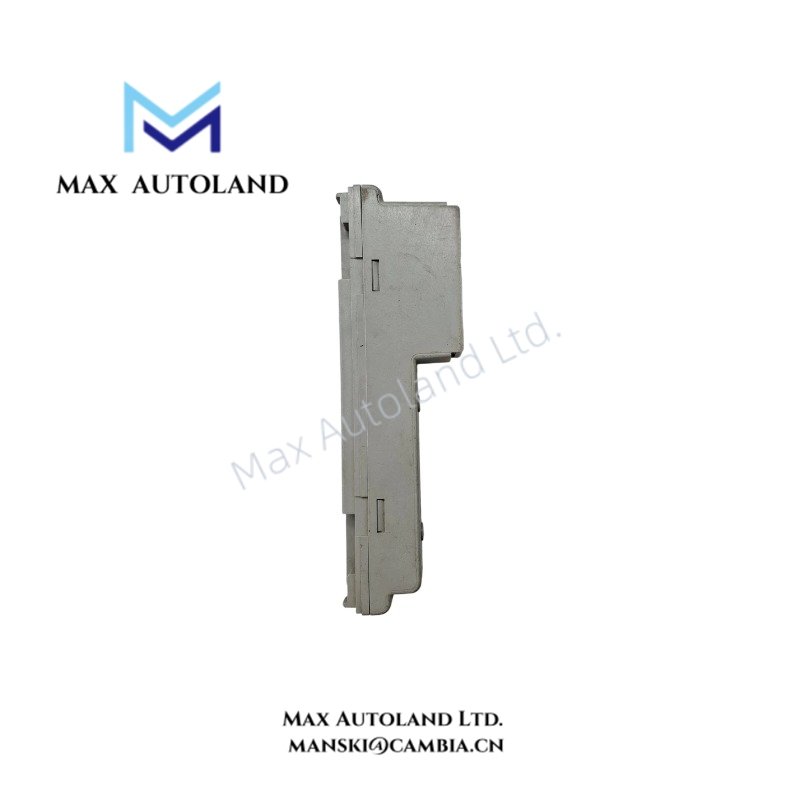
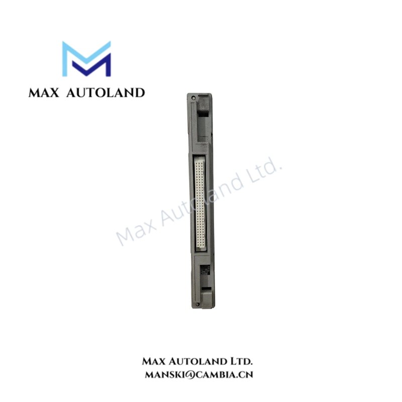
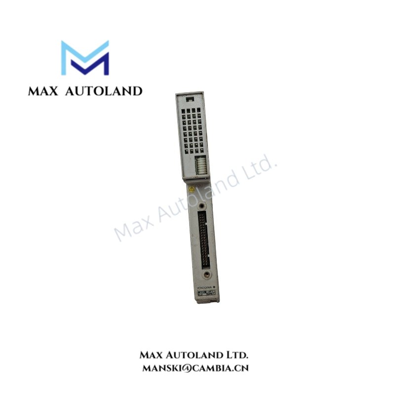
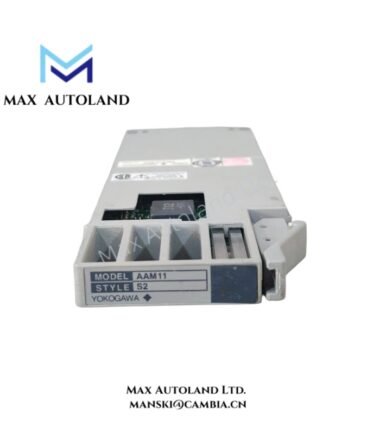
Overview
Hardware Specifications
| Parameter | Specification |
|---|---|
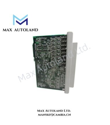
| Model | AMM12C |
| Brand | Yokogawa |
| Product Type | Voltage Input Multiplexer Module |
| Input Voltage Range | -10 V to +10 V DC |
| Input Current | 20 mA max |
| Output Voltage Range | -10 V to +10 V DC |
| Output Current | 20 mA max |
| I/O Points Per Module | 16 channels |
| Switching Time | 10 ms max |
| Insulation Resistance | 100 MOhm min |
| Redundancy | Dual-redundant support options |
| Operating Temp | -10 deg C to +55 deg C / +60 deg C, depending on rack environment |
| Storage Temp | -25 deg C to +70 deg C |
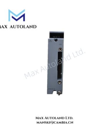
| Signal Connection | Terminal blocks |
| Power Consumption | Not specified in supplied data |
| Weight | Approx. 0.3 kg to 1.0 kg, depending on housing/shipping packaging |
| Dimensions | Not specified in supplied data |
Yokogawa Process Signal Interface
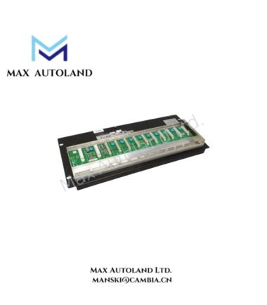
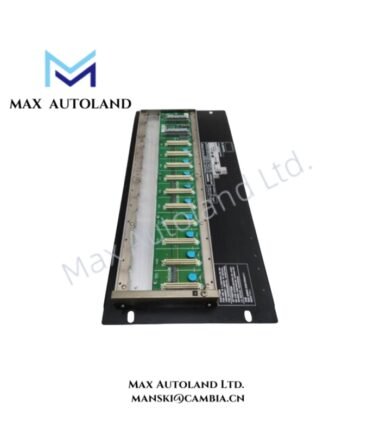
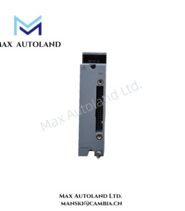
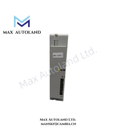
The AMM12C handles analog voltage signals between field-side wiring and the control-system signal path. Its stated input and output ranges extend from -10 V to +10 V DC, while the module provides 16 channels per module.
Channel isolation and insulation resistance support electrical separation between signal paths. Therefore, installation should maintain appropriate separation between analog wiring and power or high-noise circuits.
Frequently Asked Questions
Q: What voltage range does the AMM12C support?
A: The supplied specifications state an input and output range of -10 V to +10 V DC.
Q: How many channels does one AMM12C provide?
A: The supplied data specifies 16 I/O channels per module.
Q: What is the specified switching time?
A: The maximum stated switching time is 10 ms.
Field Installation Guidelines
Install the AMM12C in the designated Yokogawa rack or mounting environment and secure the module according to the applicable system hardware procedure. Connect field voltage signals to the specified terminal blocks and verify polarity before energization.
Route analog signal wiring separately from AC power, switching circuits, and other high-noise conductors. Where shielded cable is used, terminate the shield according to the Yokogawa system grounding specification and avoid creating unintended ground loops.
Before commissioning, verify that each connected signal remains within the specified -10 V to +10 V DC range. Also confirm terminal assignments, insulation condition, channel wiring, and rack compatibility before applying operating power.
Emerson Top Products
| Emerson DeltaV | Epro | Ovation/Westinghouse |
| KJ1501X1-BC3 | 9100-00049-03 | 1C31122G01 |
| KJ3202X1-BA1 | A6110 | 1C31125G03 |
| KJ3222X1-BA1 | A6120 | 1C31232G01 |
| KJ3243X1-BA1 | A6125 | 1C31147G01 |
| KJ3002X1-BG1 | A6140 | 1B30035H01 |
| KJ3002X1-BB1 | A6210 | 1B30023H02 |
| KJ3001X1-BB1 | A6220 | 1B30023H01 |
| KJ3002X1-BC1 | A6312 | 1C31132G01 |
| KJ3002X1-BF1 | A6312/06 | 1C31129G03 |
| KJ3001X1-BJ1 | A6312/08 | 5X00119G01 |
Customers Also Viewed
| Bently Nevada | ABB | Yokogawa | Woodward | Schneider |
| 133835-02 | SPDSM04 | CP451-10 | 5463-785 | 140CPU65150 |
| 135321-01 | SPIEET800 | CP461 | 5437-672 | BMEXBP0400 |
| 135322-01 | SPINIET800 | CP461-50 | 9907-175 | 140CPU67160 |
| 136751-01 | SPNLK01 | CP451-11 | 5466-355 | 170FNT11001 |
| 136751-02 | SPSED01 | CP701 S1 | 5466-257 | 170ADO34000 |
| 184139-10 | SPSEM11 | CP345 S1 | 5466-1049 | 170ADM35010 |
| 82362-01 | SPSET01 | SCP461-11 S1 | 5501-381 | 170ADI34000 |
| 84134-01 | SPTKM01 | CP451-10 S2 | 8200-177 | 140ARI03010 |
| 87900-02 | SPTPS02 | CP401-10 | 8200-205 | BMXCPS4002 |
| 89998-01 | SPTPS13 | NFCP100-S00 | 9907-029 | 140CRP93200 |
Reviews
There are no reviews yet.