
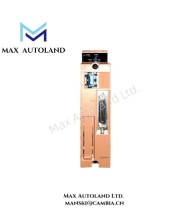
Overview
Hardware Specifications
| Parameter | Specification |
|---|---|
| Model | S9344FA |
| Brand | Yokogawa |
| Module Type | Connector Interface Module |
| ESB Bus Connection | ESB bus connectors |
| Field Connection | Field wiring terminals |
| Origin | Japan |
| Weight | 0.05 kg |
| Dimensions | 3.2 x 2.5 x 11.1 cm (estimated shipping size) |
| Power Supply | 5 V DC |
| Power Consumption | 2-8 W (typical) |
| Isolation | 500-1500 V AC |
| Operating Temp | 0 deg C to +60 deg C |
| Humidity | 10-90% RH, non-condensing |
| Tariff Code | 8537101190 |
| Place of Shipment | Xiamen, China |
ESB Bus and Field Wiring Interface
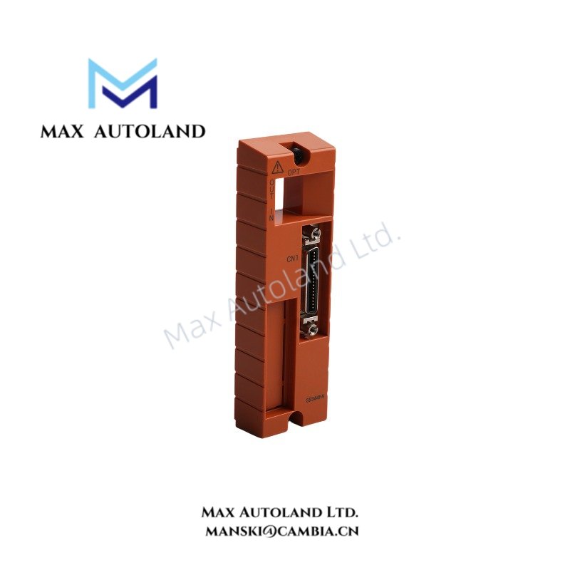
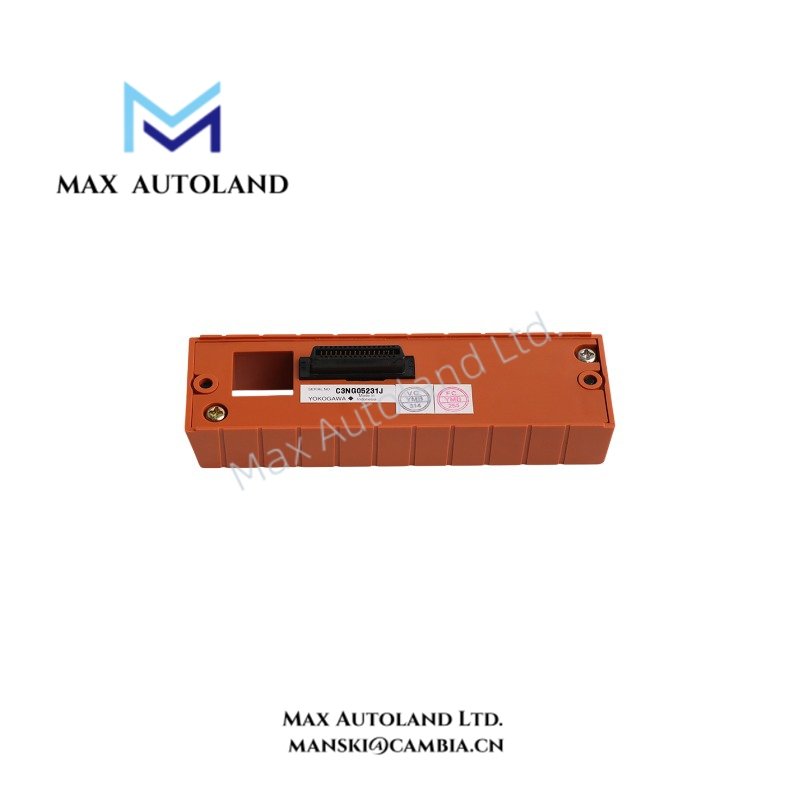
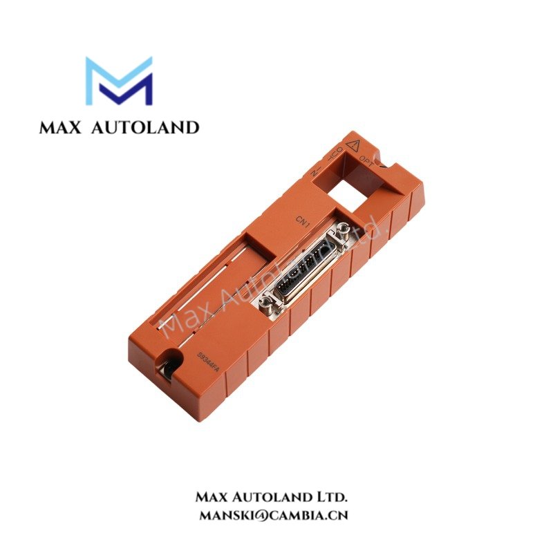
The S9344FA provides connector interfaces for ESB bus connections and field wiring terminals. These physical connection points support the interconnection of compatible control hardware and field wiring.
The specified 5 V DC power supply defines the module’s supply requirement. Meanwhile, the stated isolation range is 500-1500 V AC. The available specifications do not identify individual isolation channels or their electrical configuration.
For installation, verify connector compatibility and terminal assignments against the applicable Yokogawa system documentation.
Frequently Asked Questions
Q: What connections does the Yokogawa S9344FA provide?
A: The S9344FA provides ESB bus connectors and field wiring terminals.
Q: What power supply does the S9344FA require?
A: The specified power supply is 5 V DC, with typical power consumption of 2-8 W.
Q: What are the specified operating environment limits?
A: The operating temperature range is 0 deg C to +60 deg C. Humidity must remain between 10% and 90% RH, non-condensing.
Field Installation Guidelines
- Verify the S9344FA model designation and connector configuration before installation.
- Confirm that the mounting position accommodates the module and its connected wiring.
- Inspect ESB bus connectors and field wiring terminals for physical damage or contamination.
- Connect the ESB bus and field wiring according to the applicable Yokogawa system wiring documentation.
- Verify the specified 5 V DC supply before energizing the module.
- Route signal wiring separately from power conductors where practical to reduce electrical interference.
- Apply appropriate cable shielding and grounding practices according to the system installation documentation.
- Maintain the specified operating temperature and non-condensing humidity conditions.
- Inspect terminal connections and connector engagement before commissioning.
YOKOGAWA Top Products
| CPU | Power Supply and Battery | Rack |
| SCP451-51 | S9562FA | A1BD5D-06 |
| CP461-10 S1 | S9564FA | A1BR4D-05 |
| CP330D S3 | S9345FA | AKB337-M020 |
| CP461-50 S2 | S9548FA | NFBU200-015 |
| SCP451-53 | S9260DE-01 | NFBU200-S10 |
| SCP401-11 | S9971DB-0 | SNT411-13 |
| S2CP471-01 | S9681DB | SED2D-01 |
| CP451-51 | S9841DA | NFAF135-S00 |
| CP471-01 | SPW484-53 | NFAI835-S50 |
| CP461-53 | NFPW442-50 | NFAI543-H00 |
Customers Also Viewed
| Bently Nevada | ABB | GE Fanuc | Honeywell | Invensys |
|---|---|---|---|---|
| 330101-00-40-05-02-00 | PM591-2ETH | IS200ECTBG2A | CC-TDIL11 | FBM223 |
| 330101-00-40-10-02-00 | PM595-4ETH-F | IS200EPCTG1AZZ | CC-IP0101 | FBM207b |
| 330101-00-40-10-02-05 | DX522 | IS200VRTDH1DAA | CC-PAIX01 | FBM206 |
| 330101-00-43-15-02-05 | AX521 | IS200ERIOH1ACB | CC-TCNT01 | FBM237 |
| 330101-00-52-15-02-05 | AX522 | IS200ERQCH1A | CC-TAOX01 | FBM217 |
| 330101-00-55-05-02-05 | DI524 | IS200EACFG1BAA | CC-PDIS01 | FBM215 |
| 330101-00-55-10-02-05 | DI561 | IS200TVIBH2B | CC-PAIX01 | FBM211 |
| 330101-00-67-10-12-CN | DI562 | IS415UCVGH1A | CC-PAIH01 | FBM207 |
| 330101-00-75-15-02-05 | DI571 | IS200JPDDG1AAA | CC-PUIO31 | FBM223 |
| 330101-00-79-15-02-05 | DI581-S | IS200SPROH1ADD | CC-TAIX51 | FBM231 |


Reviews
There are no reviews yet.