
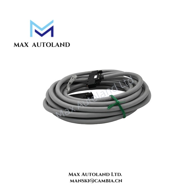

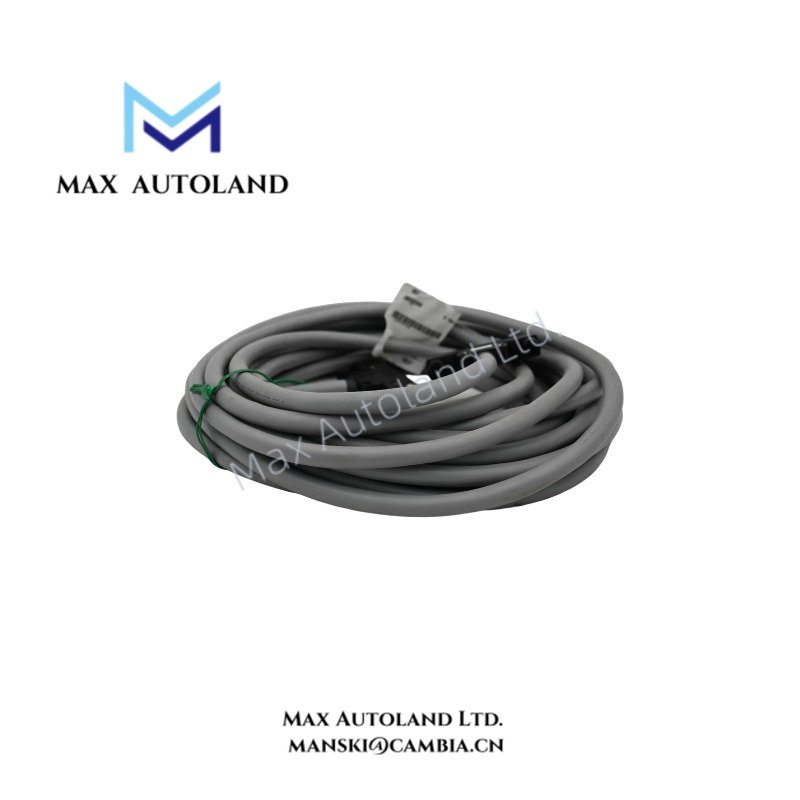
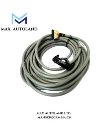
Overview
Hardware Specifications
| Parameter | Specification |
|---|---|
| Model | KS10-20*A |
| Base Model | KS10 |
| Brand | Yokogawa |
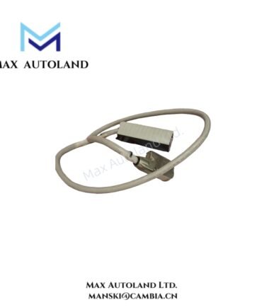
| Product Type | Signal Cable / I/O Cable |
| Cable Length | 20 m |
| Suffix Code | *A – Standard style version |
| Shielding | Overall braided/foil shielding |
| Compatibility | Yokogawa CENTUM DCS, ProSafe-RS |
| Application | I/O module to terminal board interconnection |
| Core Function | Signal transmission between I/O modules and terminal assemblies |
Shielding and Signal Transmission
The KS10-20*A uses overall braided or foil shielding to reduce electromagnetic interference during signal transmission. Consequently, the shielding helps limit external electrical noise coupling into the cable conductors.
For installation, maintain separation between signal cables and high-current power conductors. Additionally, terminate the cable shield according to the grounding requirements of the connected Yokogawa system and terminal assembly.
The cable provides a physical signal path; it does not independently perform signal conversion, amplification, or protocol processing.
Frequently Asked Questions (FAQ)
**Q: What is the specified cable length of the Yokogawa KS10-20*A?**
A: The model designation indicates a cable length of 20 m.
**Q: Does the KS10-20*A include shielding?**
A: Yes. The supplied specification identifies overall braided/foil shielding for electromagnetic interference suppression.
**Q: Can the KS10-20*A connect directly to Yokogawa I/O modules?**
A: The cable is specified for interconnection between Yokogawa system I/O modules and corresponding external terminal boards or connection units. Verify connector compatibility and the applicable system wiring documentation before installation.
Field Installation Guidelines
- Verify the connection points: Confirm that the cable connectors match the designated I/O module and terminal board interfaces.
- Inspect the cable assembly: Check the connector housings, cable jacket, and accessible shielding for physical damage before installation.
- Route the cable appropriately: Keep signal wiring separated from power conductors and sources of electromagnetic interference.
- Maintain shielding continuity: Follow the system-specific grounding instructions for the cable shield and connected terminal assembly.
- Avoid mechanical stress: Prevent excessive bending, pulling, twisting, or compression during cable routing.
- Verify connections: Confirm connector engagement and inspect the completed wiring before restoring system operation.
YOKOGAWA Top Products
| CPU | Power Supply and Battery | Rack |
| SCP451-51 | S9562FA | A1BD5D-06 |
| CP461-10 S1 | S9564FA | A1BR4D-05 |
| CP330D S3 | S9345FA | AKB337-M020 |
| CP461-50 S2 | S9548FA | NFBU200-015 |
| SCP451-53 | S9260DE-01 | NFBU200-S10 |
| SCP401-11 | S9971DB-0 | SNT411-13 |
| S2CP471-01 | S9681DB | SED2D-01 |
| CP451-51 | S9841DA | NFAF135-S00 |
| CP471-01 | SPW484-53 | NFAI835-S50 |
| CP461-53 | NFPW442-50 | NFAI543-H00 |
Customers Also Viewed
| Bently Nevada | ABB | GE Fanuc | Honeywell | Invensys |
|---|---|---|---|---|
| 330101-00-40-05-02-00 | PM591-2ETH | IS200ECTBG2A | CC-TDIL11 | FBM223 |
| 330101-00-40-10-02-00 | PM595-4ETH-F | IS200EPCTG1AZZ | CC-IP0101 | FBM207b |
| 330101-00-40-10-02-05 | DX522 | IS200VRTDH1DAA | CC-PAIX01 | FBM206 |
| 330101-00-43-15-02-05 | AX521 | IS200ERIOH1ACB | CC-TCNT01 | FBM237 |
| 330101-00-52-15-02-05 | AX522 | IS200ERQCH1A | CC-TAOX01 | FBM217 |
| 330101-00-55-05-02-05 | DI524 | IS200EACFG1BAA | CC-PDIS01 | FBM215 |
| 330101-00-55-10-02-05 | DI561 | IS200TVIBH2B | CC-PAIX01 | FBM211 |
| 330101-00-67-10-12-CN | DI562 | IS415UCVGH1A | CC-PAIH01 | FBM207 |
| 330101-00-75-15-02-05 | DI571 | IS200JPDDG1AAA | CC-PUIO31 | FBM223 |
| 330101-00-79-15-02-05 | DI581-S | IS200SPROH1ADD | CC-TAIX51 | FBM231 |




Reviews
There are no reviews yet.