
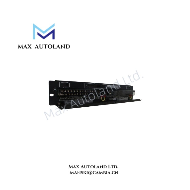
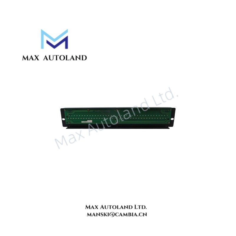
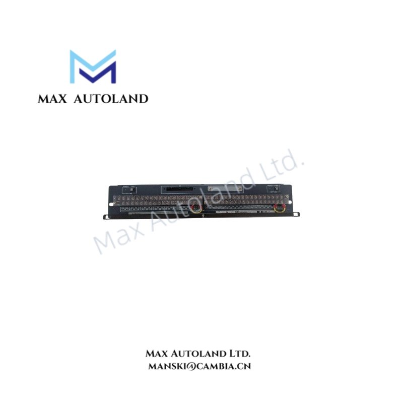
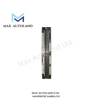
Overview
Suffix Breakdown & Model Matrix
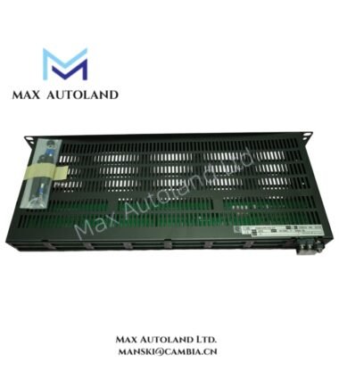
Single ordered model: AED5D-00. No additional suffix segmentation or variant encoding defined in provided source data.
Hardware Specifications
| Parameter | Specification |
|---|---|
| ModelBrand | Yokogawa AED5D-00 |
| Origin | Japan |
| Weight | 1.5 kg |
| Signal Interface | Digital I/O termination for ADV series modules |
| Channel Capacity | 32 points (as referenced configuration) |
| Mounting Method | Screw terminal block (M4) |
| Compatible Modules | ADV151, ADV161, ADV551, ADV561, AKB331, AKB337 |
Yokogawa Field Signal Termination Characteristics
Channel-Level Signal Routing and Isolation Behavior
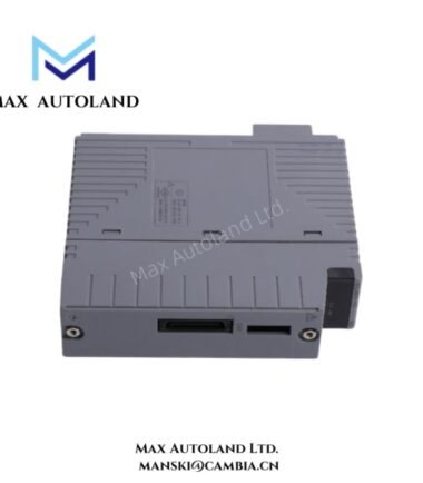
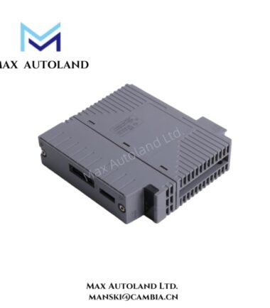
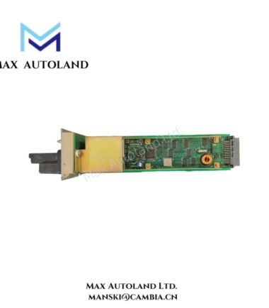
The AED5D-00 terminal board implements passive field termination for Yokogawa ADV-series digital input/output modules. Signal integrity is maintained through structured point-to-point screw termination, reducing wiring ambiguity across 32-point digital signal groups. The design supports structured separation of field wiring from backplane logic processing, ensuring stable electrical referencing for multi-channel discrete signal acquisition and output distribution within DCS I/O racks.
Frequently Asked Questions
Q: Does AED5D-00 support hot-swap operation?
A: No active switching logic is implemented on the terminal board. Wiring disconnection requires de-energized field conditions to avoid signal interruption or terminal stress.
Q: What is the backplane interaction mechanism?
A: The unit itself does not perform backplane processing. It functions as a passive termination interface between field wiring and ADV-series I/O modules.
Q: Can mixed-voltage digital signals be applied on adjacent terminals?
A: Electrical separation depends on system wiring design and external module constraints. Terminal spacing supports standard industrial segregation practices only.
Field Installation Guidelines
Ensure system power is isolated prior to wiring termination. All field conductors must be tightened to M4 terminal torque specifications consistent with industrial control panel standards. Maintain physical separation between signal cables and power conductors to reduce induced noise coupling. Shield grounding should be executed at a single reference point within the control cabinet to avoid ground loop formation. Verify continuity of all 32 termination points before system energization. Mechanical mounting must ensure rigid fixation to prevent vibration-induced loosening under continuous operation.
Emerson Top Products
| Emerson DeltaV | Epro | Ovation/Westinghouse |
| KJ1501X1-BC3 | 9100-00049-03 | 1C31122G01 |
| KJ3202X1-BA1 | A6110 | 1C31125G03 |
| KJ3222X1-BA1 | A6120 | 1C31232G01 |
| KJ3243X1-BA1 | A6125 | 1C31147G01 |
| KJ3002X1-BG1 | A6140 | 1B30035H01 |
| KJ3002X1-BB1 | A6210 | 1B30023H02 |
| KJ3001X1-BB1 | A6220 | 1B30023H01 |
| KJ3002X1-BC1 | A6312 | 1C31132G01 |
| KJ3002X1-BF1 | A6312/06 | 1C31129G03 |
| KJ3001X1-BJ1 | A6312/08 | 5X00119G01 |
Customers Also Viewed
| Bently Nevada | ABB | Yokogawa | Woodward | Schneider |
| 133835-02 | SPDSM04 | CP451-10 | 5463-785 | 140CPU65150 |
| 135321-01 | SPIEET800 | CP461 | 5437-672 | BMEXBP0400 |
| 135322-01 | SPINIET800 | CP461-50 | 9907-175 | 140CPU67160 |
| 136751-01 | SPNLK01 | CP451-11 | 5466-355 | 170FNT11001 |
| 136751-02 | SPSED01 | CP701 S1 | 5466-257 | 170ADO34000 |
| 184139-10 | SPSEM11 | CP345 S1 | 5466-1049 | 170ADM35010 |
| 82362-01 | SPSET01 | SCP461-11 S1 | 5501-381 | 170ADI34000 |
| 84134-01 | SPTKM01 | CP451-10 S2 | 8200-177 | 140ARI03010 |
| 87900-02 | SPTPS02 | CP401-10 | 8200-205 | BMXCPS4002 |
| 89998-01 | SPTPS13 | NFCP100-S00 | 9907-029 | 140CRP93200 |

Reviews
There are no reviews yet.