
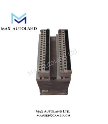
Overview
Hardware Specifications
| Parameter | Specification |
|---|---|
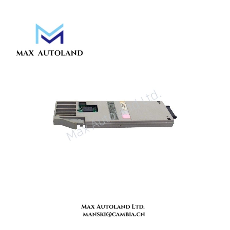
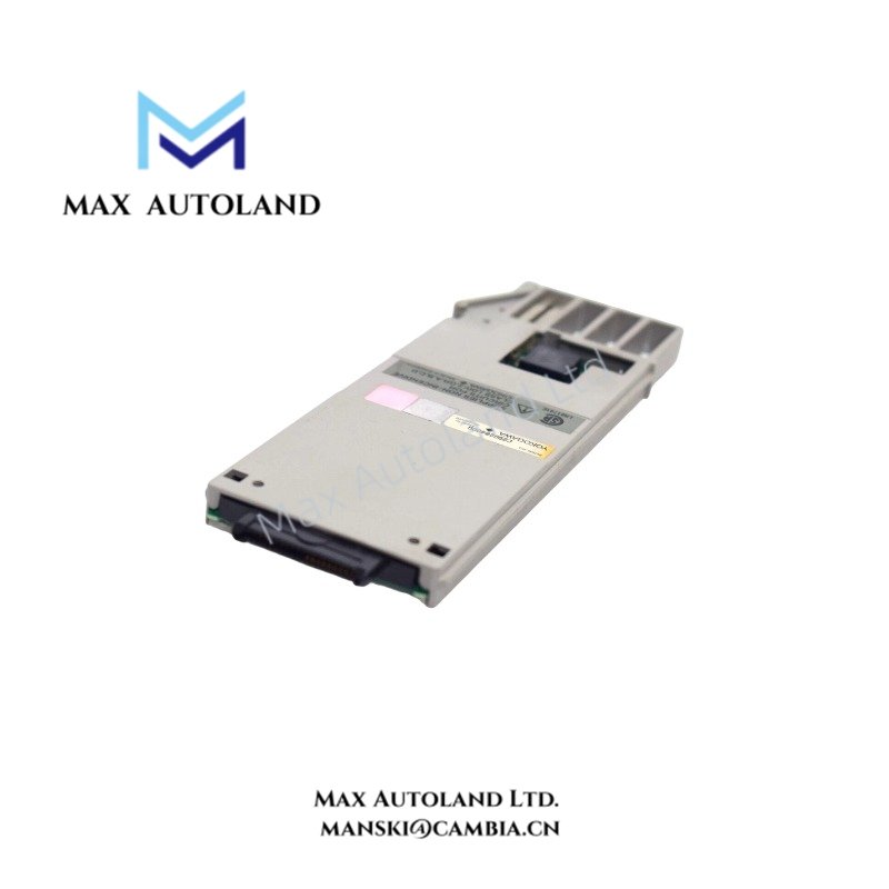
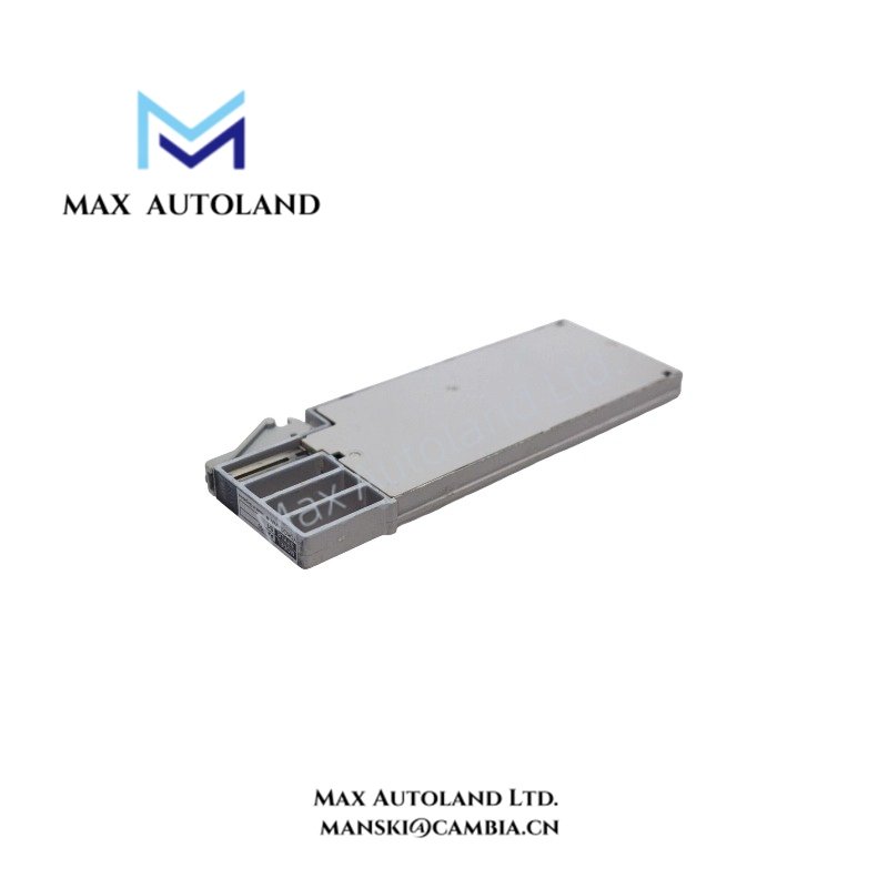
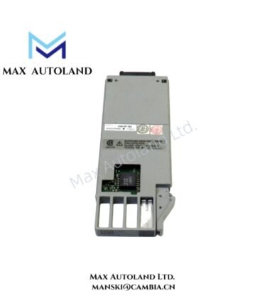
| Model | AAM50 |
| Spare Model | STYLE 2 |
| Brand | Yokogawa |
| Product Type | Current Output Module |
| Function | Current Output |
| Hardware Style | S1 |
| Chipset | J12 |
| Origin | Japan |
| Weight | 0.1 kg |
| Dimensions | 7.6 cm x 2.5 cm x 17.8 cm |
| Tariff Code | 8538907080 |
| Manufacturer Status | Discontinued by manufacturer |
Current Output and DCS Interface
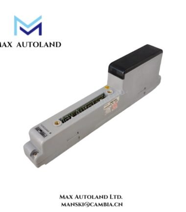
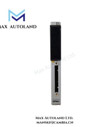
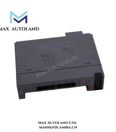
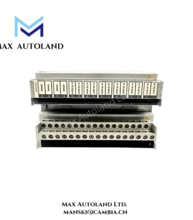
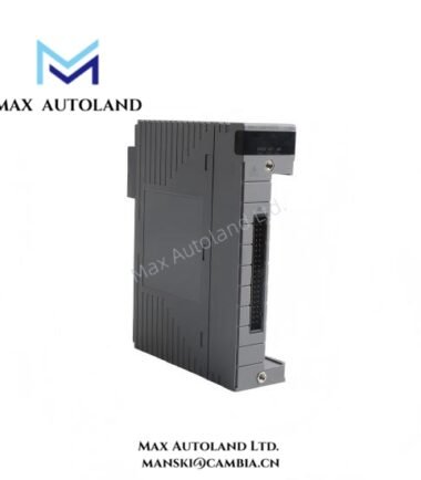
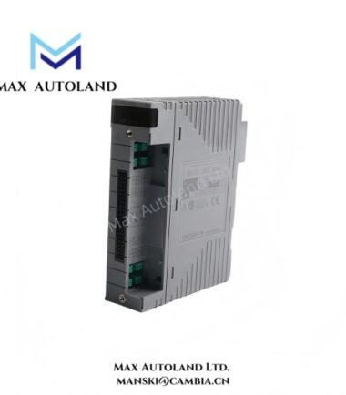
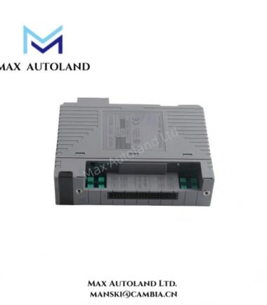
The AAM50 performs current output functions within the connected Yokogawa I/O hardware. The module converts control-side output data into an electrical current signal for the connected field circuit.
The supplied technical data does not specify the output current range, channel count, electrical isolation, load resistance, accuracy, or communication protocol. Therefore, these values should be verified against the applicable Yokogawa hardware documentation before circuit replacement or commissioning.
Frequently Asked Questions
Q: What output function does the AAM50 provide?
A: The AAM50 is identified as a Current Output Module. The supplied data does not specify the exact output current range.
Q: What hardware configuration identifies this unit?
A: The supplied data identifies the hardware as S1 style with a J12 chipset and lists STYLE 2 as the spare model.
Q: What are the operating temperature and power consumption specifications?
A: The supplied information does not provide operating-temperature or power-consumption values. Do not substitute assumed values during engineering verification.
Field Installation Guidelines
Verify the module model, hardware style, and chipset designation before installation. Confirm that the replacement unit matches the existing I/O assembly and associated wiring.
Isolate the relevant control-system power and field circuit before removing the module. Follow the applicable Yokogawa installation procedure for module extraction and insertion.
Check terminal identification against the system drawings before reconnecting field wiring. Keep current-signal wiring separated from high-voltage power conductors and high-noise switching circuits where the installation design permits.
Connect cable shields according to the site grounding design and Yokogawa system documentation. Avoid creating unintended ground loops through multiple shield termination points.
After installation, inspect the module seating and connector engagement. Restore power according to the system startup procedure, then verify the current output circuit from the control-system side through the connected field device.
Emerson Top Products
| Emerson DeltaV | Epro | Ovation/Westinghouse |
| KJ1501X1-BC3 | 9100-00049-03 | 1C31122G01 |
| KJ3202X1-BA1 | A6110 | 1C31125G03 |
| KJ3222X1-BA1 | A6120 | 1C31232G01 |
| KJ3243X1-BA1 | A6125 | 1C31147G01 |
| KJ3002X1-BG1 | A6140 | 1B30035H01 |
| KJ3002X1-BB1 | A6210 | 1B30023H02 |
| KJ3001X1-BB1 | A6220 | 1B30023H01 |
| KJ3002X1-BC1 | A6312 | 1C31132G01 |
| KJ3002X1-BF1 | A6312/06 | 1C31129G03 |
| KJ3001X1-BJ1 | A6312/08 | 5X00119G01 |
Customers Also Viewed
| Bently Nevada | ABB | Yokogawa | Woodward | Schneider |
| 133835-02 | SPDSM04 | CP451-10 | 5463-785 | 140CPU65150 |
| 135321-01 | SPIEET800 | CP461 | 5437-672 | BMEXBP0400 |
| 135322-01 | SPINIET800 | CP461-50 | 9907-175 | 140CPU67160 |
| 136751-01 | SPNLK01 | CP451-11 | 5466-355 | 170FNT11001 |
| 136751-02 | SPSED01 | CP701 S1 | 5466-257 | 170ADO34000 |
| 184139-10 | SPSEM11 | CP345 S1 | 5466-1049 | 170ADM35010 |
| 82362-01 | SPSET01 | SCP461-11 S1 | 5501-381 | 170ADI34000 |
| 84134-01 | SPTKM01 | CP451-10 S2 | 8200-177 | 140ARI03010 |
| 87900-02 | SPTPS02 | CP401-10 | 8200-205 | BMXCPS4002 |
| 89998-01 | SPTPS13 | NFCP100-S00 | 9907-029 | 140CRP93200 |
Reviews
There are no reviews yet.