

Overview
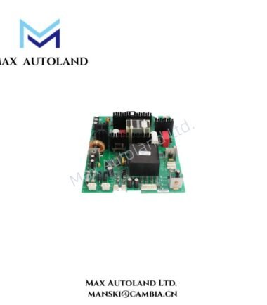
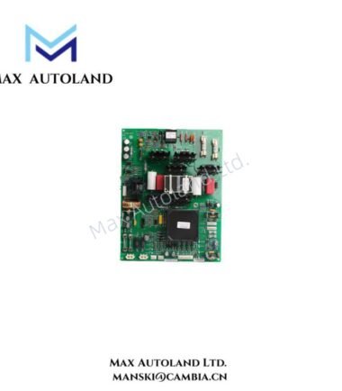
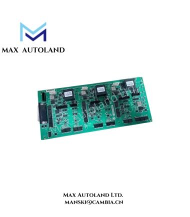
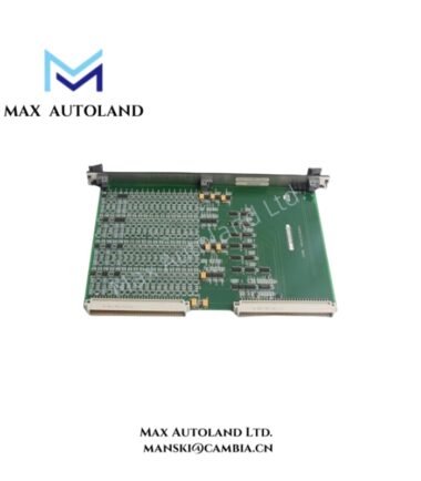
The IS200EISBH1AAB is an Exciter ISBus Board manufactured by General Electric for the EX2100 excitation control system. It provides communication interfaces between the M1, M2, and C controllers and the DSPX controller. Furthermore, it handles fiber-optic feedback signals and supports communication between the controller system, engineering tools, and keypad through RS-232C connections.
Functional Description
The Exciter ISBus Board (EISB) provides communication functions within the EX2100 control rack. It receives and transmits fiber-optic feedback signals, then transfers this information through the control backplane to the DSPX controller.
In addition, the board supports communication between the DSPX controller and the tool and keypad ports through RS-232C via the backbone connector. For redundant exciter configurations, its ISBus interface electronics transfer data among the M1, M2, and C controllers using GE’s proprietary ISBus communication interface.
Rack Position and Signal Interfaces
The EISB is a single-slot, 3U-high module installed in the control rack below the DSPX controller. Its front-panel fiber-optic connectors provide interfaces for current and voltage feedback signals from the generator field and, when required, from the exciter through FDCE boards.
Furthermore, the six front-panel fiber-optic connectors handle generator field voltage and current feedback, optional exciter voltage and current feedback, and ground detection signals. Fiber-optic transmission provides electrical isolation between the EISB and high-voltage measurement circuits.
Communication Interfaces
The board uses several communication paths for signal exchange:
- ISBus: GE proprietary communication interface for data exchange among the M1, M2, and C controllers.
- Fiber-optic interfaces: Receive and transmit feedback signals between the EISB, feedback boards, and ground detection circuitry.
- RS-232C: Provides serial communication with the engineering tool and keypad ports.
- Control backplane: Transfers communication data between the EISB and DSPX controller.
The RS-232C tool interface supports data rates from 1,200 to 38,400 baud. In addition, the board receives its 24 VDC supply and return through the backplane.
Technical Specifications
| Parameter | Specification |
|---|---|
| Model | IS200EISBH1AAB |
| Brand | General Electric (GE) |
| Series | EX2100 |
| Product Type | Exciter ISBus Board (EISB) |
| Board Function | Communication Interface |
| Controller Interfaces | M1, M2, C |
| Communication Bus | GE proprietary ISBus |
| Serial Interface | RS-232C |
| RS-232C Data Rate | 1,200 to 38,400 baud |
| Fiber-Optic Connectors | 6 |
| Backplane Power Supply | 24 VDC |
| Module Form Factor | Single-slot, 3U |
| Mounting Location | EX2100 control rack, below DSPX |
| Ground Detection Interface | Ground Detection Module (EGDM) |
| Manual | GEI-100454 |
| Country of Origin | United States |
| Availability | In Stock |
| Repair Lead Time | 3-7 days |
Frequently Asked Questions
Q: What is the main function of the IS200EISBH1AAB?
A: It manages fiber-optic communication and ISBus data exchange within the EX2100 excitation control system. It also provides RS-232C communication interfaces for the engineering tool and keypad.
Q: Where is the EISB installed in the EX2100 system?
A: It occupies a single 3U slot in the control rack directly below the DSPX controller. The EISB and DSPX are mechanically arranged together in the rack.
Q: What is the purpose of the six fiber-optic connectors?
A: They handle generator field voltage and current feedback, optional exciter feedback, and ground detection signals. These optical connections provide electrical isolation from high-voltage measurement circuits.