Overview
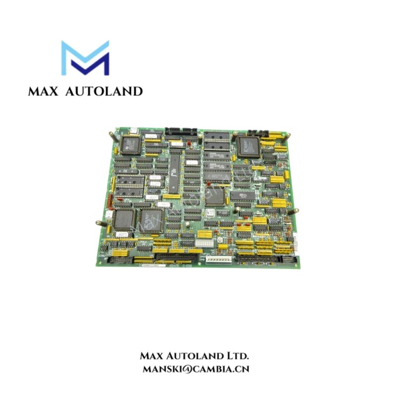
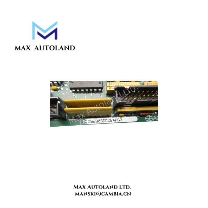
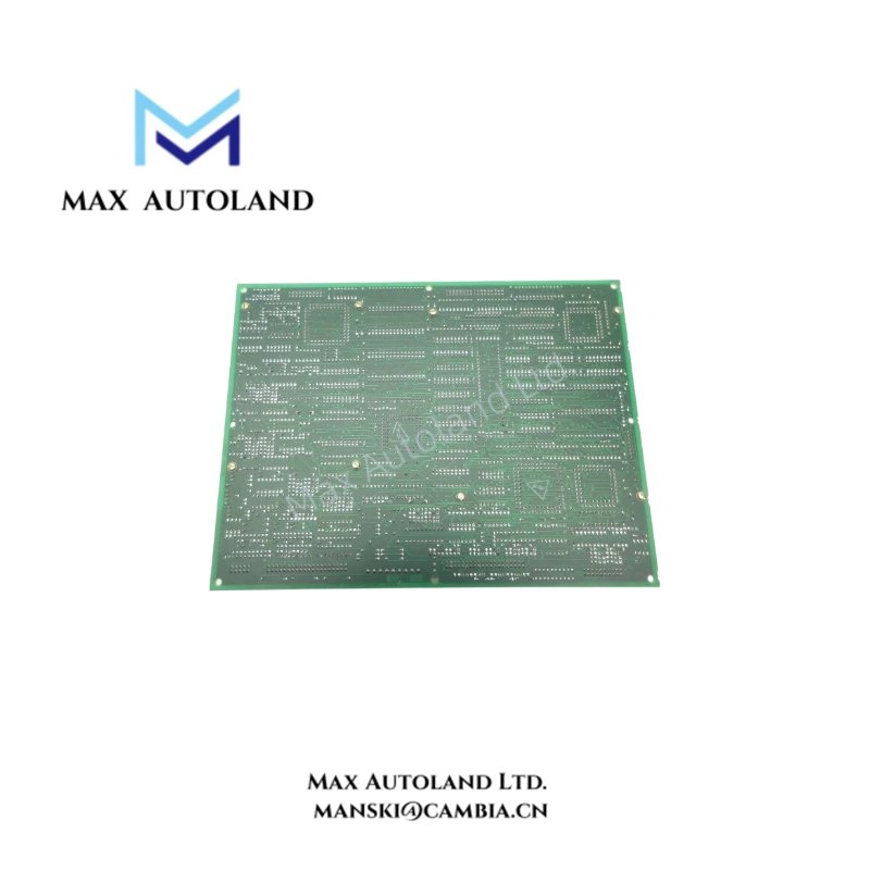
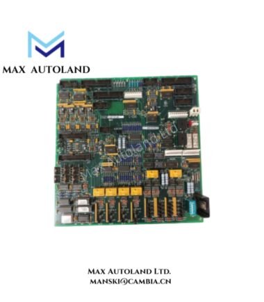
The GE DS200SDCCG4AGD Drive Control Board is a control circuit board designed for the Mark V Turbine Control System. It serves as the primary drive controller and uses three microprocessors with shared-access RAM to process different control functions. Furthermore, the board provides connections to the Power Supply Interface Board and supports LED-based operating status and fault-code indication.
Technical Specifications
| Parameter | Specification |
|---|---|
| Model | DS200SDCCG4AGD |
| Brand | GE General Electric |
| Series | Mark V |
| Product Type | Drive Control Board |
| Functional Acronym | SDCC |
| Functional Description | Drive Control Card |
| Instruction Manual | GEI-100029 |
| PCB Coating | Normal Coating |
| Functional Revision 1 | A |
| Functional Revision 2 | G |
| Artwork Revision | D |
| Microprocessors | 3 |
| RAM | Shared-access RAM |
Drive Control and Processing
The DS200SDCCG4AGD acts as the primary controller for the drive assembly. Its three microprocessors handle specific board functions, while the shared-access RAM allows multiple processors to access memory during operation.
This processing arrangement supports the board’s drive control functions within the Mark V system. In addition, the board connects with optional cards and other drive control boards through dedicated connectors.
Power Supply Interface Connections
The board has two connectors for connection to the Power Supply Interface Board. Each connector serves a different purpose:
- I/O signal connection: Transfers input and output signals between the Drive Control Board and Power Supply Interface Board.
- DC voltage connection: Receives DC voltage from the Power Supply Interface Board.
These separate connections provide the signal and power paths required by the board. Therefore, both connections should be considered when checking the board configuration and interface wiring.
LED Status and Fault Diagnostics
The DS200SDCCG4AGD features 10 LEDs arranged in a row for operating status and diagnostic indication. During normal operation, the LEDs flash sequentially from left to right. They maintain this pattern when the drive receives power but is not running.
If the board detects an error, the LEDs display a fault code through different flashing groups:
- First 2 LEDs: Indicate the hundreds digit.
- Next 4 LEDs: Indicate the tens digit.
- Final 4 LEDs: Indicate the units digit.
Furthermore, the LEDs can be configured to display drive variables. Maintenance personnel can observe these indicators from the front of the drive cabinet when the door is open.
Safety note: The drive may contain hazardous electrical energy even when it is not running. Contact with internal components can cause electric shock or burns. Follow the applicable isolation and electrical safety procedures before inspecting the board.
Model Identification
The DS200SDCCG4AGD belongs to the DS200SDCCG4 product group within the Mark V platform. Its identification includes the SDCC functional acronym, normal PCB coating, and three revision designations.
The A and G functional revisions and D artwork revision identify the board configuration. Maintenance personnel should check the complete part number and revision markings when sourcing a replacement to avoid configuration mismatches.
Frequently Asked Questions
Q: What is the function of the GE DS200SDCCG4AGD?
A: It is a Drive Control Board that serves as the primary controller for the drive assembly in the GE Mark V system. It uses three microprocessors and shared-access RAM to process board functions.
Q: How many LEDs are available on the DS200SDCCG4AGD?
A: The board has 10 LEDs arranged in a row. They indicate normal operating status, fault codes, and configurable drive variables.
Q: What is the purpose of the two Power Supply Interface Board connectors?
A: One connector carries I/O signals, while the other receives DC voltage from the Power Supply Interface Board. They provide separate signal and power connections.