

Overview
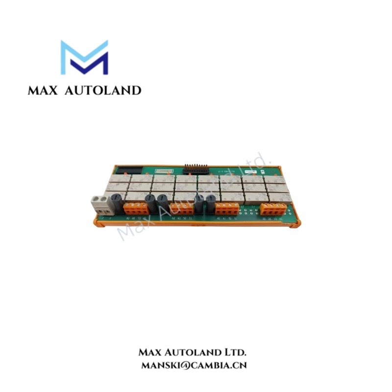
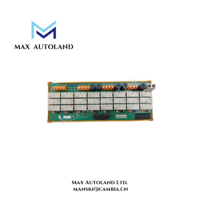
The Honeywell FC-TSRO-08UNI, also cataloged as the FC-TSRO-08UNI relay output field termination assembly, operates as a dedicated hardware component for safe external power relay switching within Safety Instrumented Systems. This 8-channel FTA interfaces control logic with high-voltage field loads up to 250 VAC/VDC, featuring fused normally open (NO) field contacts and channel-level status indication LEDs for SIL3-rated loop applications.
Hardware Specifications
| Parameter | Specification |
|---|---|
| Model | FC-TSRO-08UNI |
| Brand | Honeywell |
| Country of Origin | USA |
| Weight | 0.14 kg |
| Estimated Dimensions | 9 x 7 x 5.5 cm |
| Nominal Input Voltage | 24 VDC |
| Max. Input Voltage | 36 VDC |
| Relay Pick-up Voltage | 19.2 VDC |
| Input Current | Typically 40 mA at 24 VDC |
| Number of Output Channels | 8 |
| Max. Output Current | 2 A (fused, 2 AT slow-acting) |
| Min. Output Current | 1 mA at 5 V |
| Max. Output Voltage | 250 VAC / 250 VDC |
| Safety Rating | Up to SIL3 |
| Approvals | CE, UL, CSA, TUV |
Channel Isolation and SIS Loop Integrity
Engineered for high-integrity safety instrumented functions, the module maintains strict channel-to-channel separation to prevent common-cause failure vectors across safety loops. The integration of fused normally open (NO) field contacts utilizing 2 AT slow-acting elements ensures deterministic fault containment during overcurrent conditions. Galvanic separation between the 24 VDC control side and the 115/230 VAC field switching side suppresses electromagnetic interference (EMI) and transient voltage propagation, preserving loop availability and fault-state execution thresholds up to SIL3 compliance.
Frequently Asked Questions
Q: What is the maximum continuous current rating per output channel on the FC-TSRO-08UNI FTA?
A: Each channel supports a maximum continuous current of 2 A, restricted by the integrated 2 AT slow-acting field fuse.
Q: How is the relay pick-up state verified during operation?
A: Each output channel features a dedicated status indication LED wired in parallel with the relay coil circuit to provide visual verification of actuation when input voltage exceeds 19.2 VDC.
Field Installation Guidelines
- Ensure all external power feeds and 24 VDC control signals are completely isolated and locked out prior to wiring termination.
- Mount the FTA within a suitably rated industrial enclosure to protect internal components from moisture, conductive dust, and mechanical shock.
- Verify that field cable shields and drain wires are properly terminated to the designated chassis ground bus to maintain EMC performance.
- Inspect fuse integrity and ensure correct torque is applied to all screw terminal blocks to prevent high-resistance connections under thermal load.


Reviews
There are no reviews yet.