

Overview
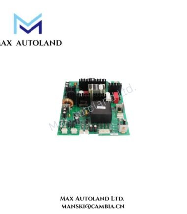
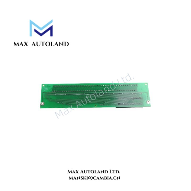
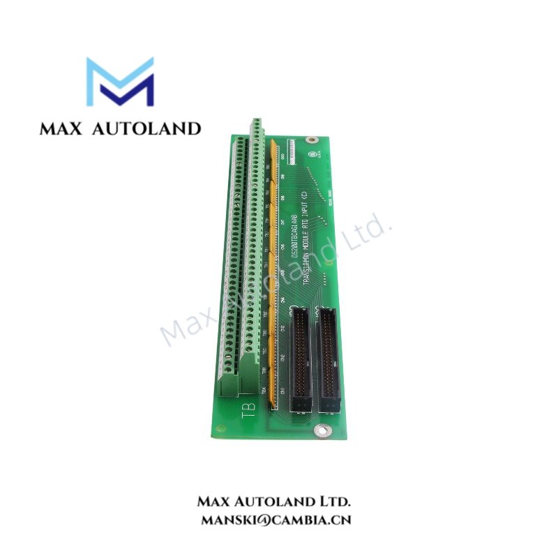
The GE DS200TBCAG1AAA, also identified by the base model DS200TBCAG1, is a thermocouple interface board associated with the GE Mark V turbine control system. It provides the hardware interface for thermocouple input signals used in temperature measurement. The supplied information identifies its board function but does not confirm channel count, thermocouple types, input ranges, or onboard cold junction compensation specifications.
Hardware Specifications
| Parameter | Specification |
|---|---|
| Model | DS200TBCAG1AAA |
| Brand | GE |
| Series | Mark V / Speedtronic |
| Product Type | Thermocouple Interface Board |
| Origin | USA |
| Primary Function | Thermocouple signal interface |
| Signal Type | Thermocouple millivolt signals |
| Tariff Code | 8537101190 |
Thermocouple Signal Interface Characteristics
Thermocouples generate low-level voltage signals that correspond to temperature differences between the measurement junction and the reference junction. The DS200TBCAG1AAA is identified in the supplied description as a thermocouple interface board for the Mark V system.
Before integration, verify the thermocouple input configuration, terminal assignments, signal polarity, and reference-junction compensation method against the applicable GE documentation. Do not assume that the board provides onboard cold junction compensation or supports specific thermocouple types without model-specific documentation.
Frequently Asked Questions
Q: Which thermocouple types does the DS200TBCAG1AAA support?
A: The supplied information does not establish the supported thermocouple types. Confirm sensor compatibility and input configuration using the applicable GE Mark V hardware documentation.
Q: Does the DS200TBCAG1AAA provide onboard cold junction compensation?
A: This function is not verified by the available information. Check the board schematic or technical manual to determine how reference-junction compensation is implemented.
Q: Can the board be replaced while the Mark V system is energized?
A: Hot-swap capability is not confirmed. Follow the manufacturer-approved shutdown, isolation, and replacement procedures before removing or installing the board.
Field Installation Guidelines
- Verify the complete part number, including the suffix AAA, against the existing board and equipment documentation.
- Isolate the applicable equipment according to site electrical safety procedures before handling the board.
- Record terminal assignments and thermocouple wiring polarity before disconnecting field conductors.
- Route thermocouple wiring separately from power cables and high-noise switching circuits to reduce electromagnetic interference.
- Apply cable shielding and grounding practices specified by the system design. Avoid introducing unintended ground loops.
- Inspect connectors, terminals, and board contacts for damage before installation.
- After installation, verify wiring continuity, sensor polarity, temperature readings, and controller diagnostics according to the approved commissioning procedure.