

Overview
Hardware Specifications
| Parameter | Specification |
|---|---|
| Model | F3BU13-ON |
| Base Model | F3BU13 |
| Brand | Yokogawa Electric Corporation |
| Product Type | FA-M3 Base Module |
| System | FA-M3 |
| Number of Slots | 13 |
| Number of I/O Slots | 12 |
| Weight | 470 g |
| Power Consumption | 50 mA at 5 V DC |
| Power Supply Slot Allocation | Slots for power supply are excluded from the 12 I/O slots |
FA-M3 Backplane and Module Arrangement
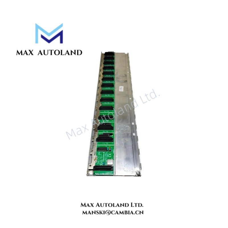
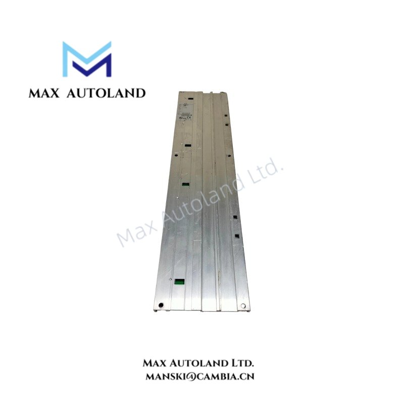
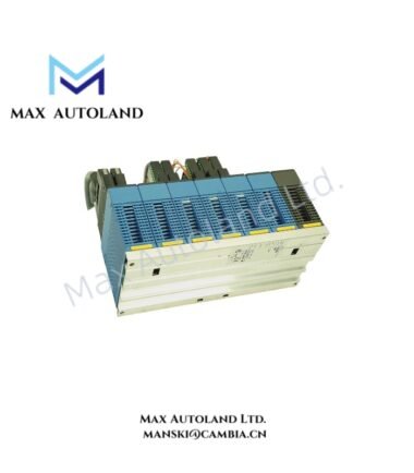
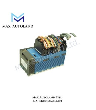
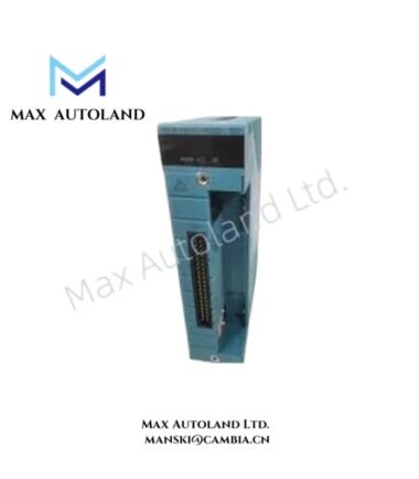
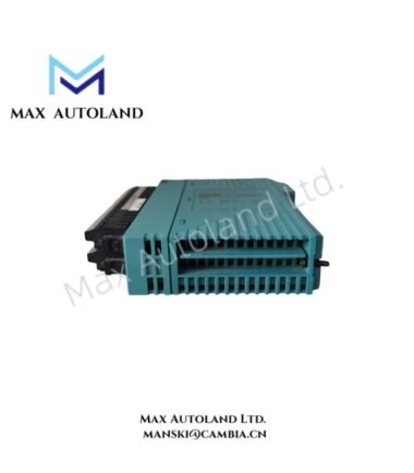
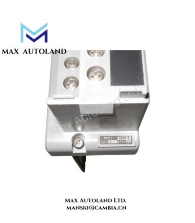
The F3BU13-ON provides the physical mounting structure for FA-M3 modules. Its 13-slot configuration accommodates the module arrangement required by the target control system.
The specification identifies 12 usable I/O slots when a single CPU module operates in the system. Therefore, engineers should account for CPU and power-supply slot requirements when assigning modules to the base.
The FA-M3 base module range includes 4-, 5-, 6-, 9-, 13-, and 16-slot versions. Yokogawa specifies no distinction between main units and sub-units for these base modules.
Frequently Asked Questions
Q: How many slots does the F3BU13-ON provide?
A: The F3BU13-ON provides 13 total slots. Yokogawa specifies 12 I/O slots that can be used with a single CPU module.
Q: What current does the F3BU13-ON consume?
A: The specified current consumption is 50 mA at 5 V DC.
Q: Does the F3BU13-ON include 13 I/O slots?
A: No. The model provides 13 total slots, while the specified number of usable I/O slots is 12. The I/O slot count excludes the slot allocation for the power supply.
Field Installation Guidelines
Install the F3BU13-ON on the designated FA-M3 mounting structure and secure the base before inserting system modules. Verify that the available slot arrangement matches the CPU, power supply, and I/O module configuration.
Before installation, isolate system power and inspect the backplane connectors for contamination or mechanical damage. Align each module with its assigned slot and apply even insertion force to prevent connector damage.
Route power and signal wiring separately where practical. Maintain appropriate separation between low-level signal wiring and sources of electrical noise. For shielded signal cables, terminate the shield according to the applicable FA-M3 system wiring design and site grounding scheme.
Confirm the installed module positions against the control-system configuration before energizing the system. Also verify that the 5 V DC current load remains within the capacity of the selected FA-M3 power arrangement.
Emerson Top Products
| Emerson DeltaV | Epro | Ovation/Westinghouse |
| KJ1501X1-BC3 | 9100-00049-03 | 1C31122G01 |
| KJ3202X1-BA1 | A6110 | 1C31125G03 |
| KJ3222X1-BA1 | A6120 | 1C31232G01 |
| KJ3243X1-BA1 | A6125 | 1C31147G01 |
| KJ3002X1-BG1 | A6140 | 1B30035H01 |
| KJ3002X1-BB1 | A6210 | 1B30023H02 |
| KJ3001X1-BB1 | A6220 | 1B30023H01 |
| KJ3002X1-BC1 | A6312 | 1C31132G01 |
| KJ3002X1-BF1 | A6312/06 | 1C31129G03 |
| KJ3001X1-BJ1 | A6312/08 | 5X00119G01 |
Customers Also Viewed
| Bently Nevada | ABB | Yokogawa | Woodward | Schneider |
| 133835-02 | SPDSM04 | CP451-10 | 5463-785 | 140CPU65150 |
| 135321-01 | SPIEET800 | CP461 | 5437-672 | BMEXBP0400 |
| 135322-01 | SPINIET800 | CP461-50 | 9907-175 | 140CPU67160 |
| 136751-01 | SPNLK01 | CP451-11 | 5466-355 | 170FNT11001 |
| 136751-02 | SPSED01 | CP701 S1 | 5466-257 | 170ADO34000 |
| 184139-10 | SPSEM11 | CP345 S1 | 5466-1049 | 170ADM35010 |
| 82362-01 | SPSET01 | SCP461-11 S1 | 5501-381 | 170ADI34000 |
| 84134-01 | SPTKM01 | CP451-10 S2 | 8200-177 | 140ARI03010 |
| 87900-02 | SPTPS02 | CP401-10 | 8200-205 | BMXCPS4002 |
| 89998-01 | SPTPS13 | NFCP100-S00 | 9907-029 | 140CRP93200 |


Reviews
There are no reviews yet.