
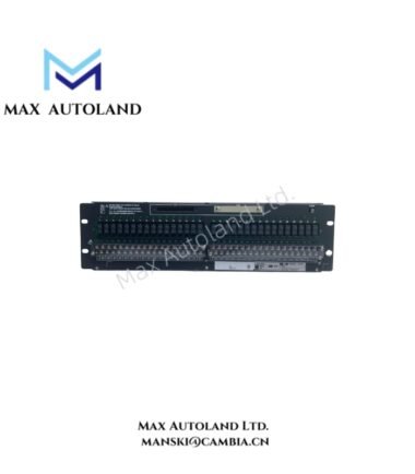
Overview
Output Function and Signal Handling
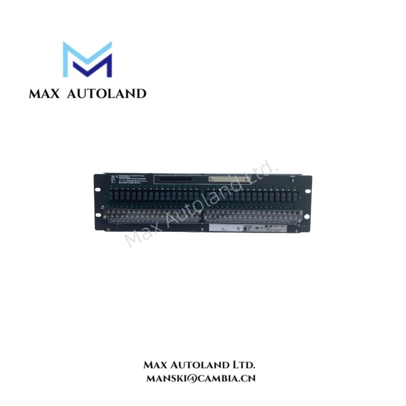
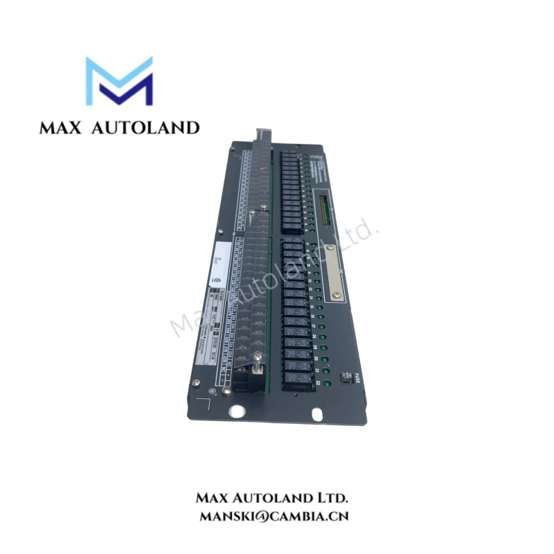
The ARM55D-000 receives digital output signals from the FIO digital output module and switches the corresponding field circuits through mechanical relay contacts. The relay contacts provide electrical isolation between the control-side circuitry and field device connections.
Each of its 32 output points uses an NO (normally open) contact. The board supports single and dual-redundant configurations, allowing it to operate with the corresponding redundant digital I/O arrangement.
Compatible Modules and Connections
The specified module and connection configurations include:
- ADV551: 32-point digital output module, used with the ATD5A terminal block.
- ADV561: 64-point digital output module.
- AKB331: Signal cable for 32-point configurations.
- AKB337: Signal cable for 64-point configurations.
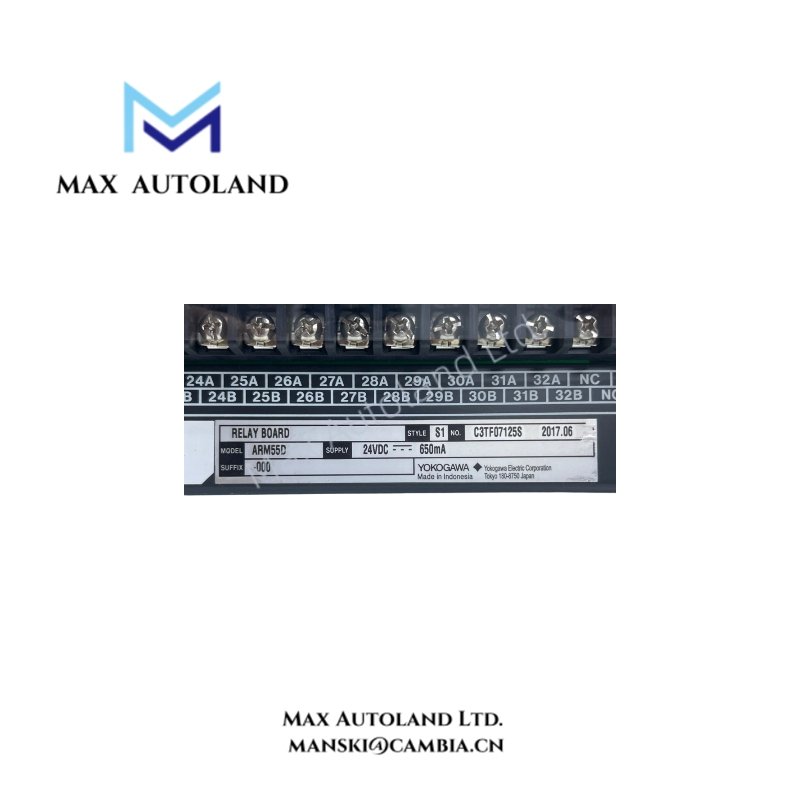
Furthermore, the field device connections use M4 screw terminals. The board requires an external 24 VDC supply for its internal circuitry, with a maximum current consumption of 0.65 A.
Electrical Ratings and Operating Conditions
The maximum contact load depends on the applied voltage. For AC and low-voltage DC circuits, the contacts support up to 2 A per point. However, the maximum load decreases to 0.1 A per point at 125 VDC. Therefore, the load voltage and current must both be checked when selecting field devices.
The minimum specified load is 5 V and 10 mA. In addition, the board provides insulation resistance of at least 10 MOhm at 500 VDC, with separate withstand voltage ratings between the field terminals, power terminals, and board case.
Technical Specifications
| Parameter | Specification |
|---|---|
| Model | ARM55D-000 |
| Brand | Yokogawa |
| Product Type | Mechanical Relay Board |
| System | CENTUM VP FIO Subsystem |
| Output Type | Mechanical Relay, Dry Contact |
| Contact Configuration | Normally Open (NO), “a” contact |
| Output Points | 32 points |
| Redundancy | Single / Dual redundant |
| Field Device Terminals | M4 screw terminals |
| Compatible I/O Module | ADV551 (32-point) |
| Additional Module Configuration | ADV551 + ATD5A Terminal Block |
| Additional I/O Module | ADV561 (64-point) |
| Signal Cable | AKB331 (32-point) |
| Signal Cable | AKB337 (64-point) |
| Maximum AC Load | 250 VAC, 2 A per point |
| Maximum DC Load | 30 VDC, 2 A per point |
| Maximum DC Load | 125 VDC, 0.1 A per point |
| Minimum Load | 5 V, 10 mA |
| Internal Circuit Power Supply | 24 VDC, external supply required |
| Maximum Current Consumption | 0.65 A |
| Field Device Power Supply | External supply required; not provided by the board |
| Insulation Resistance | At least 10 MOhm at 500 VDC |
| Withstand Voltage (Field Terminals to Case) | 2 kV |
| Withstand Voltage (24 V Power Terminals to Case) | 500 V |
| Withstand Voltage (24 V Power to Field Terminals) | 2 kV |
| Ambient Temperature | 0 to 50 deg C |
| Ambient Humidity | 10 to 90 %RH |
| Safety Standard | CSA |
| EMC Standards | CE Marking, C-Tick Marking |
| Dimensions (W x H) | 482.6 x 132.5 mm (3U) |
| Weight | 2.2 kg |
Frequently Asked Questions
Q: What type of output does the Yokogawa ARM55D-000 provide?
A: It provides 32 mechanical relay dry contact outputs. Each output uses a normally open (NO) contact for switching external field device circuits.
Q: Does the ARM55D-000 support dual redundancy?
A: Yes. The board supports both single and dual-redundant configurations for FIO digital I/O applications.
Q: What external power supply does the ARM55D-000 require?
A: It requires an external 24 VDC supply for its internal circuitry, with a maximum current consumption of 0.65 A. The board does not provide a power supply for field devices.
YOKOGAWA Top Products
Customers Also Viewed


Reviews
There are no reviews yet.