
Overview
Hardware Specifications
| Parameter | Specification |
|---|---|
| Model | DIO264-C |
| Part Number | 00009205-00 |
| Brand | Bachmann electronic |
| Product Type | CAN Slave Digital Input/Output Module |
| System | M200 Controller System / Distributed CAN Modules |
| Origin | Austria |
| Operating Temp | -30 deg C to +60 deg C |
| Storage Temp | -40 deg C to +85 deg C |
| Operating Humidity | 5 % to 95 %, noncondensing |
| Storage Humidity | 5 % to 95 %, with condensation |
| Pollution Degree | 2 according to IEC 60664-1 |
| Supply Voltage | 18 V DC to 34 V DC |
| Power Consumption | Typ. 100 mA at 24 V DC, excluding I/O load |
| Digital Inputs | 32 |
| Input Delay | < 3.5 ms |
| Input Internal Resistance | 6 kOhm |
| Input Status Indication | Green LED |
| Configurable Digital I/O | 32 |
| Maximum Digital I/O Channels | 64 total channels |
| Nominal Output Current | 1 A per output |
| Maximum Output Current per Block | 12 A |
| Output Switching Frequency | Max. 500 Hz |
| Output Protection | Short-circuit-proof |
| Isolated Output Blocks | 1-16 and 17-32 |
| Output Status Indication | Green LED |
| CAN Interface | CAN / CANopen |
| CAN Transfer Rate | 10 kbit/s to 1000 kbit/s |
| CAN Connections | 2 x 9-pin D-sub, In/Out |
| CAN Interfaces | Internally connected for cable loop-through |
| Module ID | 1 to 254 |
| CAN Galvanic Isolation | 500 V |
| Terminating Resistor | 123 Ohm, external |
| CAN Protocols | CAL / CANopen |
| Communication Profile | DS 301 |
| Device Profile | DS 401 |
| External Supply Reverse Polarity Protection | Yes |
| Status LEDs | RUN, INIT, ERROR |
| Mounting | EN 50022 backplane |
| Wiring | Direct wiring without additional backplane |
| Approvals | CE, UKCA, cULus |
| Marine Approvals | ABS, BV, DNV, KR, LR, NK, RINA |
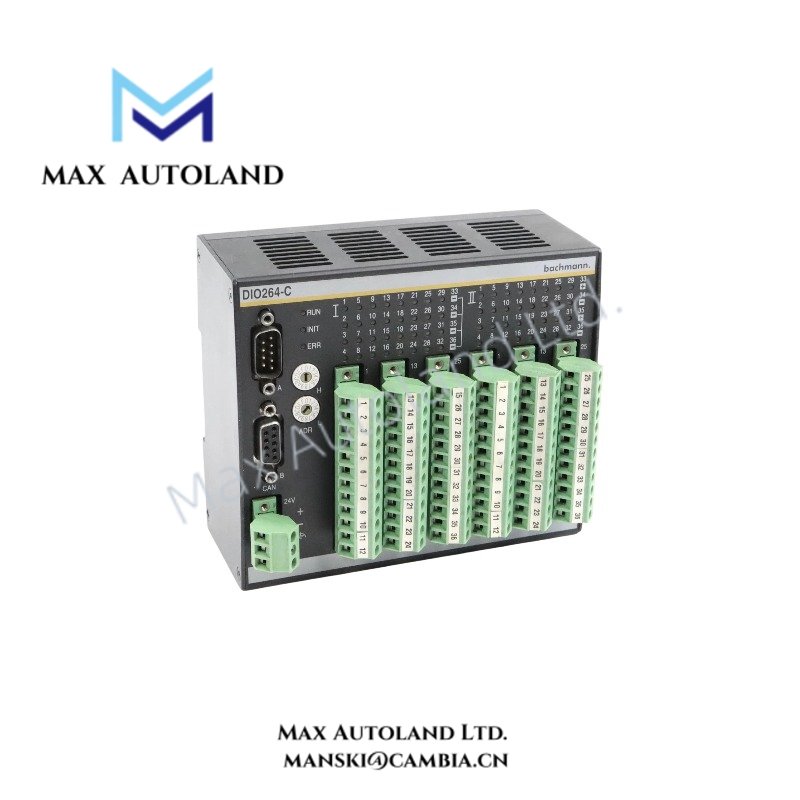
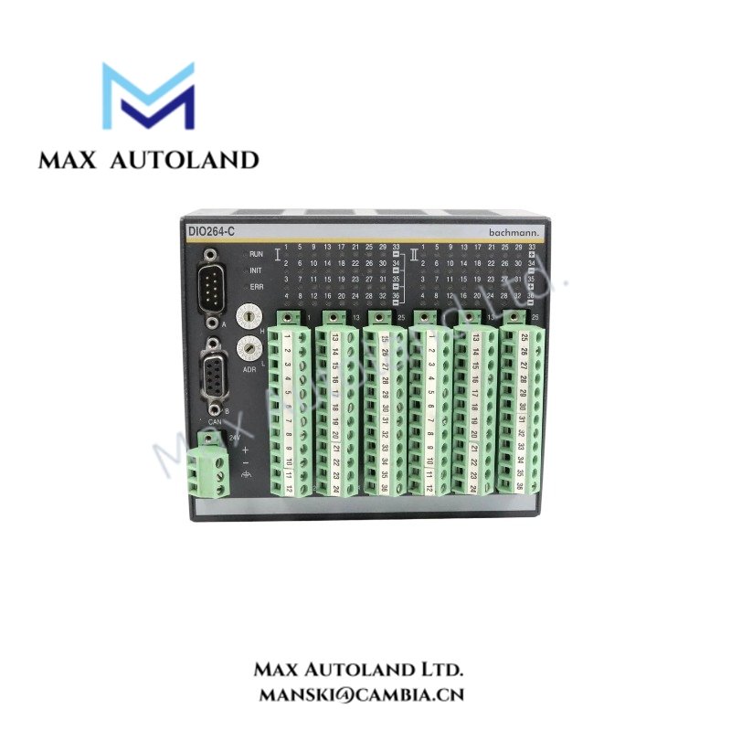
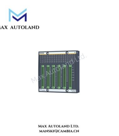
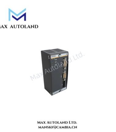
The DIO264-C provides 32 fixed digital inputs and 32 digital I/O channels. The configurable channels can operate as inputs or outputs, while each digital output supports a nominal 1 A continuous current. (Bachmann electronic GmbH)
I/O Density and Distributed CAN Communication
The module combines 64 digital channels with a distributed CAN interface, allowing the controller to exchange I/O data without a local I/O backplane. The two CAN interfaces remain internally connected, so the module can pass the CAN cable through the device. (Bachmann electronic GmbH)
Furthermore, the CAN interface supports transfer rates from 10 kbit/s to 1000 kbit/s. The module ID ranges from 1 to 254, while an external terminating resistor handles CAN bus termination. Galvanic isolation between the CAN interfaces and control electronics is specified at 500 V.
The 32 configurable I/O channels are divided into two isolated output blocks, channels 1-16 and 17-32. Each output provides 1 A nominal current, with a maximum summed block current of 12 A. Short-circuit protection is provided at the output stage.
The module supports CANopen communication according to the DS 301 communication profile and DS 401 device profile. Baud rate and node ID can be configured through the module’s rotary switches. (IEN)
Frequently Asked Questions (FAQ)
Q: How many digital channels does the DIO264-C provide?
A: The module provides 32 dedicated digital inputs plus 32 configurable digital I/O channels, giving 64 digital channels in total.
Q: Can the two CAN connectors operate as separate CAN networks?
A: No. The two 9-pin D-sub CAN interfaces are internally connected and provide cable loop-through for the CAN network.
Q: What output current can the configurable digital I/O channels provide?
A: Each digital output has a nominal current rating of 1 A. The summed output current is limited to 12 A per isolated output block.
Field Installation Guidelines
- Mount the module on the specified EN 50022 mounting system and secure the mechanical connection before wiring.
- Connect the 18 V DC to 34 V DC supply within the specified polarity and voltage range.
- Verify the external CAN terminating resistor arrangement before commissioning the network.
- Use the two D-sub connectors as CAN input and loop-through connections according to the network topology.
- Keep CAN communication wiring separated from high-current switching conductors where practical to reduce electromagnetic coupling.
- Connect cable shields according to the plant grounding concept and avoid unintended shield current paths.
- Confirm the module ID and CAN baud rate before placing the node into normal network operation.
- Verify RUN, INIT, and ERROR indications during commissioning.
- Check the output load for each isolated block and remain within the specified 12 A summed current limit.
- Do not exceed the 1 A nominal current rating of an individual digital output.
- Verify short-circuit conditions and external load wiring before enabling output channels.
- Confirm input signal response and the specified input delay during functional testing.
- Maintain the specified environmental limits during operation and storage.
Bachmann Top Products
| Bachmann | Bachmann | Bachmann |
| BS206 | ISI222 | BS210 |
| DIO216 | MPC270 | PTAI216 |
| CNT204/R | FS211/N | CNT204/H |
| PCC200 | FM211 | FS221/N |
| AIO288 | DIO248 | MPC240 |
| NT255 | FM221 | MX213 |
| AIO288/1 | DIO232 | DIO264 |
| LM201 | DIO280 | DO232 |
| CM202 | DI232 | RS204 |
| ACR222/2 | BS204 | MX220 |
Customers Also Viewed
| Bently Nevada | ABB | Yokogawa | Woodward | Schneider |
| 133835-02 | SPDSM04 | CP451-10 | 5463-785 | 140CPU65150 |
| 135321-01 | SPIEET800 | CP461 | 5437-672 | BMEXBP0400 |
| 135322-01 | SPINIET800 | CP461-50 | 9907-175 | 140CPU67160 |
| 136751-01 | SPNLK01 | CP451-11 | 5466-355 | 170FNT11001 |
| 136751-02 | SPSED01 | CP701 S1 | 5466-257 | 170ADO34000 |
| 184139-10 | SPSEM11 | CP345 S1 | 5466-1049 | 170ADM35010 |
| 82362-01 | SPSET01 | SCP461-11 S1 | 5501-381 | 170ADI34000 |
| 84134-01 | SPTKM01 | CP451-10 S2 | 8200-177 | 140ARI03010 |
| 87900-02 | SPTPS02 | CP401-10 | 8200-205 | BMXCPS4002 |
| 89998-01 | SPTPS13 | NFCP100-S00 | 9907-029 | 140CRP93200 |



Reviews
There are no reviews yet.